Space occupation estimation method and device

A technology for calculating space and space, applied in two-dimensional position/channel control, vehicle position/route/altitude control, non-electric variable control, etc. error, improve accuracy, reduce the effect of estimation bias

Active Publication Date:
View PDF14 Cites 2 Cited by
  • Summary
  • Abstract
  • Description
  • Claims
  • Application Information

AI Technical Summary

Problems solved by technology

The inventors of the present application found that the above-mentioned solutions in the prior art have the disadvantages of low accuracy of space occupancy estimation and excessive deviation

Method used


Image

  • Space occupation estimation method and device
  • Space occupation estimation method and device
  • Space occupation estimation method and device

Examples


Embodiment 1

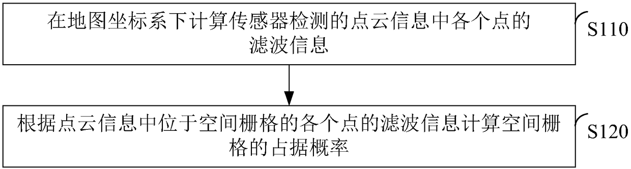
[0028] figure 1 is a flow chart of a method for estimating space occupancy according to an embodiment of the present invention, and the method can be used in an automatic driving system, such as an automatic driving system of a robot or a vehicle, such as figure 1 As shown, the method may include the following steps.

[0029] In step S110, the filter information of each point in the point cloud information detected by the sensor is calculated in the map coordinate system.

[0030] Wherein, the map coordinate system is fixed relative to the position of the sensor, and the attitude information of the point cloud information detected by the sensor is consistent in the map coordinate system and the world coordinate system.

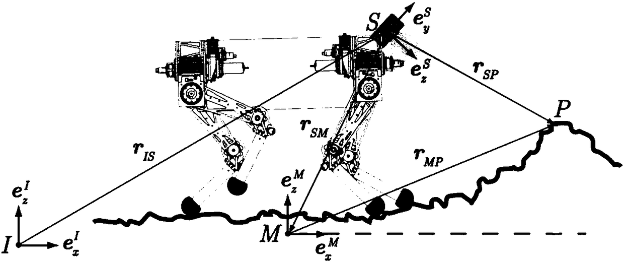
[0031] For example, in figure 2 In the environment shown, S point represents the sensor, the sensor coordinate system takes S point as the origin, and the stationary world coordinate system takes I point as the origin, r IS is the vector from point I to po...

Embodiment 2

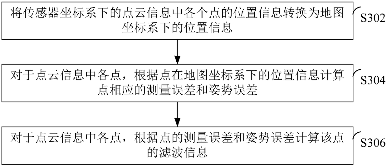
[0037] image 3 is a flowchart of the process of calculating filtering information according to an embodiment of the present invention, such as image 3 As shown, the calculation of the filter information of each point in the point cloud information detected by the sensor in the map coordinate system may include the following steps.

[0038] In step S302, the position information of each point in the point cloud information in the sensor coordinate system is converted into position information in the map coordinate system.

[0039] Wherein, the sensor coordinate system is a coordinate system established according to the position of the sensor.

[0040] For example, in figure 2 In the environment shown, the position information of the point P in the point cloud information in the map coordinate system is shown in formula 1.

[0041] P m = mr MP = mr SP -mr SM =Cms(q|t)×sr SP -mrSM Formula 1

[0042] Among them, mr MP is the position of point P in the map coordinate ...

Embodiment 3

[0053] Figure 4 is a flowchart of the process of calculating the occupancy probability of a spatial grid according to the filter information of a point according to an embodiment of the present invention, such as Figure 4 As shown, the calculation of the occupancy probability of the spatial grid according to the filtering information of each point located in the spatial grid in the point cloud information may include the following steps.

[0054] In step S402, for each point located in the spatial grid in the point cloud information, the occupancy probability of the spatial grid corresponding to the point is calculated according to the position of the point.

[0055] Further, for each point located in the spatial grid in the point cloud information, calculating the occupancy probability of the spatial grid corresponding to the point according to the position of the point may include: for each point located in the spatial grid in the point cloud information The reciprocal of...


PUM


Abstract

The embodiment of the invention provides a space occupation estimation method and device, which belong to the field of automatic driving. The method comprises steps: the filtering information of eachpoint in point cloud information detected by a sensor is calculated under a map coordinate system, wherein the position of the map coordinate system is fixed relatively to the sensor, and the attitudeinformation in the point cloud information detected by the sensor is consistent in the map coordinate system and a world coordinate system; and according to the filtering information of each point located in a space grid in the point cloud information, the space grid occupation possibility is calculated. According to the embodiment of the invention, the data under the map coordinate system relatively fixed with the sensor can be used to estimate the space occupation condition, introduced errors are reduced, the estimation accuracy is further improved, and the estimation deviation is reduced.

Description

technical field [0001] The present invention relates to the field of automatic driving, in particular to a method and device for estimating space occupation. Background technique [0002] During automatic driving, it is necessary to use sensors to detect space objects and obtain point cloud data, and then estimate the occupancy of the space based on the point cloud data. For example, when driving automatically on bumpy roads in the wild, if the GPS signal is unstable, the point cloud information can be used to estimate the space occupancy to provide prior information for path planning and object recognition. [0003] At present, the estimation of space occupancy is to convert the point cloud data in the sensor coordinate system into the data in the static world coordinate system, and estimate the space occupancy according to the data in the world coordinate system. This method introduces the cumulative translation error, Attitude error and measurement error. The inventors ...

Claims


Application Information

Patent Timeline
Patent Type & Authority Applications(China)
IPC IPC(8): G05D1/02
CPCG05D1/021
Inventor 殷鹏
Why Eureka
Try Eureka