
Conductive sliding ring brush holder system capable of automatic switching and working method thereof

A conductive slip ring and automatic switching technology, applied in the direction of circuits, current collectors, electrical components, etc., to achieve the effect of simple working principle, less manpower, and simple structure

Inactive Publication Date: 2018-07-03
浙江恩碧技创新科技有限公司
View PDF8 Cites 3 Cited by
  • Summary
  • Abstract
  • Description
  • Claims
  • Application Information

AI Technical Summary

Problems solved by technology

[0005] Purpose of the invention: In order to overcome the above deficiencies, the purpose of the present invention is to provide a conductive slip ring brush holder system that can be automatically switched, which has a simple structure, reasonable design, easy production, high degree of automation, reduced manual labor, and improved work efficiency , to solve the problem that the conductive slip ring in the prior art can automatically replace the brushes without opening the slip ring or the equipment, which saves the tedious replacement process of the previous brushes, nearly doubles the service life of the slip ring, and can also achieve saving The beneficial effect of saving time, labor and money

Method used


Image

  • Conductive sliding ring brush holder system capable of automatic switching and working method thereof
  • Conductive sliding ring brush holder system capable of automatic switching and working method thereof
  • Conductive sliding ring brush holder system capable of automatic switching and working method thereof

Examples


Embodiment

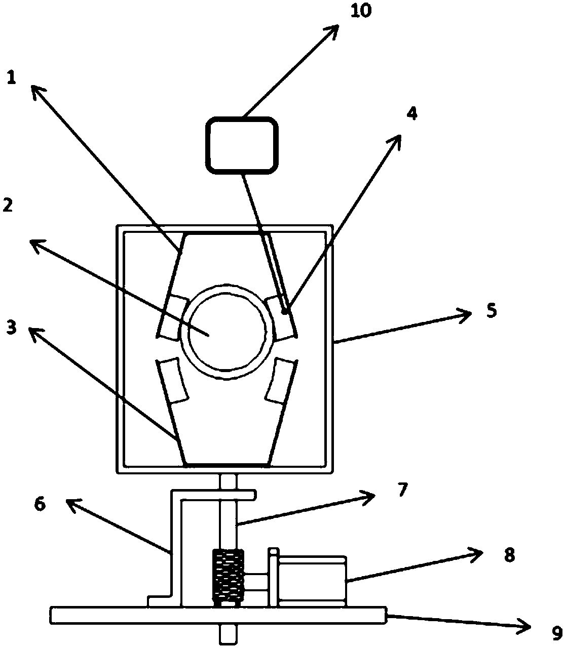
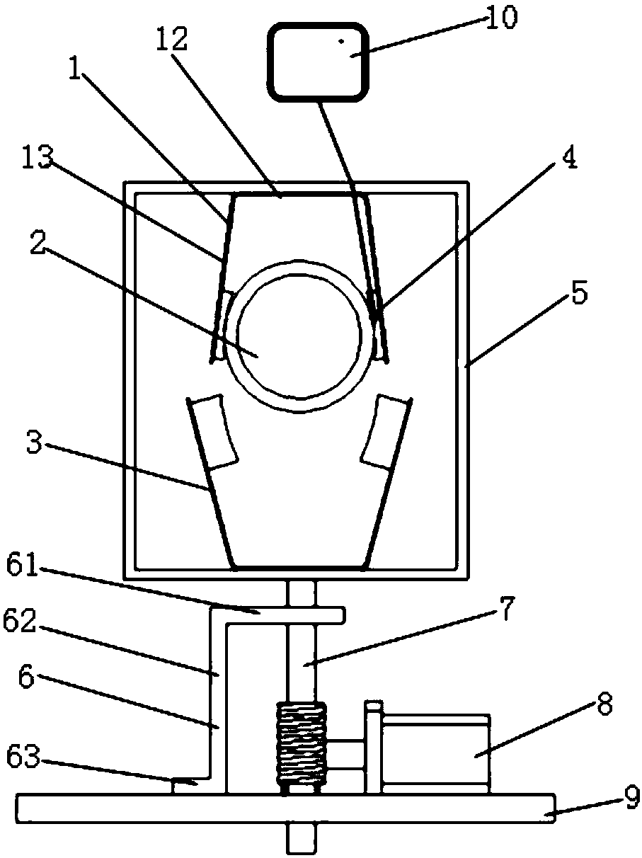
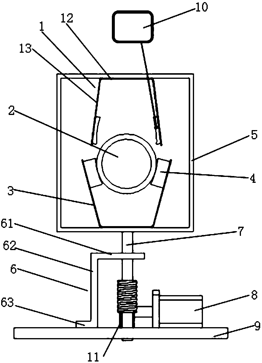
[0035] Such as Figure 1-4 The automatic switchable conductive slip ring brush holder system shown includes brush 1, conductive ring 2, spare brush 3, worn thimble 4, movable frame 5, screw rod fixing frame 6, screw rod 7, motor 8, The support plate 9, the host computer 10 and the gear 11, the brush 1 is connected to the backup brush 3, the wear thimble 4 is arranged at the end of the brush 1 and the backup brush 3 away from the conductive ring 2, the The electric brush 1 is connected with the upper end surface of the movable frame 5, the spare brush 3 is connected with the lower end surface of the movable frame 5, the lower end of the screw rod holder 6 is fixed on the support plate 9, and the screw rod 7 The upper end surface of the upper end is fixed on the outer wall of the movable frame 5, and the lower end of the screw rod 7 passes through the screw rod holder 6 and the support plate 9 in turn, the gear 11 is meshed with the screw rod 7, and the motor 8 is connected with t...


PUM


Abstract

The invention discloses a conductive sliding ring brush holder system capable of automatic switching, comprising an electric brush, a conductive ring, a backup electric brush, a wear thimble, a movable frame, a screw rod fixing frame, a screw rod, a motor, a support plate, an upper computer and a gear. The electric brush is connected with the backup electric brush. The wear thimble is disposed atend portions, away from the conductive ring, of the electric brush and the backup electric brush. The electric brush is connected with the upper end surface of the movable frame. The backup electric brush is connected with the lower end surface of the movable frame. The lower end portion of the screw rod fixing frame is fixed on the support plate. The upper end surface of the screw rod is fixed onthe outer wall of the movable frame, and the lower end portion of the screw rod passes through the screw rod fixing frame and the support plate in sequence. The gear meshes with the screw rod. The motor is connected with the gear. The upper computer is connected with the wear thimble through a signal line. The working method of the conductive sliding ring brush holder system capable of automaticswitching according to the invention is simple and easy, the conductive sliding ring does not need to be removed for maintenance, the time is greatly saved, and the work efficiency is improved.

Description

technical field [0001] The invention belongs to the technical field of conductive slip rings, in particular to an automatically switchable conductive slip ring brush holder system. The invention also relates to a working method of the automatically switchable conductive slip ring brush holder system. Background technique [0002] Conductive slip ring belongs to the application category of electrical contact sliding connection. The image, data signal and power transmission precision power transmission device of two relative rotating mechanisms are especially suitable for applications where unlimited connection and rotation are required, and at the same time power or data needs to be transmitted from a fixed position to a rotating position. [0003] At present, the market is full of various slip rings. During the operation of the slip ring, the wear of the brush and the slideway is inevitable. It can be seen that the brush is a vulnerable part. When the wear reaches a certain...

Claims


Application Information

Patent Timeline
Patent Type & Authority Applications(China)
IPC IPC(8): H01R39/38
CPCH01R39/38
Inventor 严丰曾博沈浩杰马狄峰
Owner 浙江恩碧技创新科技有限公司
Learn More