Miniscrew
A micro-screw and thread technology, which is applied in the field of micro-screws, can solve problems such as insufficient micro-screws and over-tightening of micro-screws, and achieve the effects of easy processing, guaranteed tightness of joints, and extended service life
- Summary
- Abstract
- Description
- Claims
- Application Information
AI Technical Summary
Problems solved by technology
Method used
Image
Examples
Embodiment approach 1
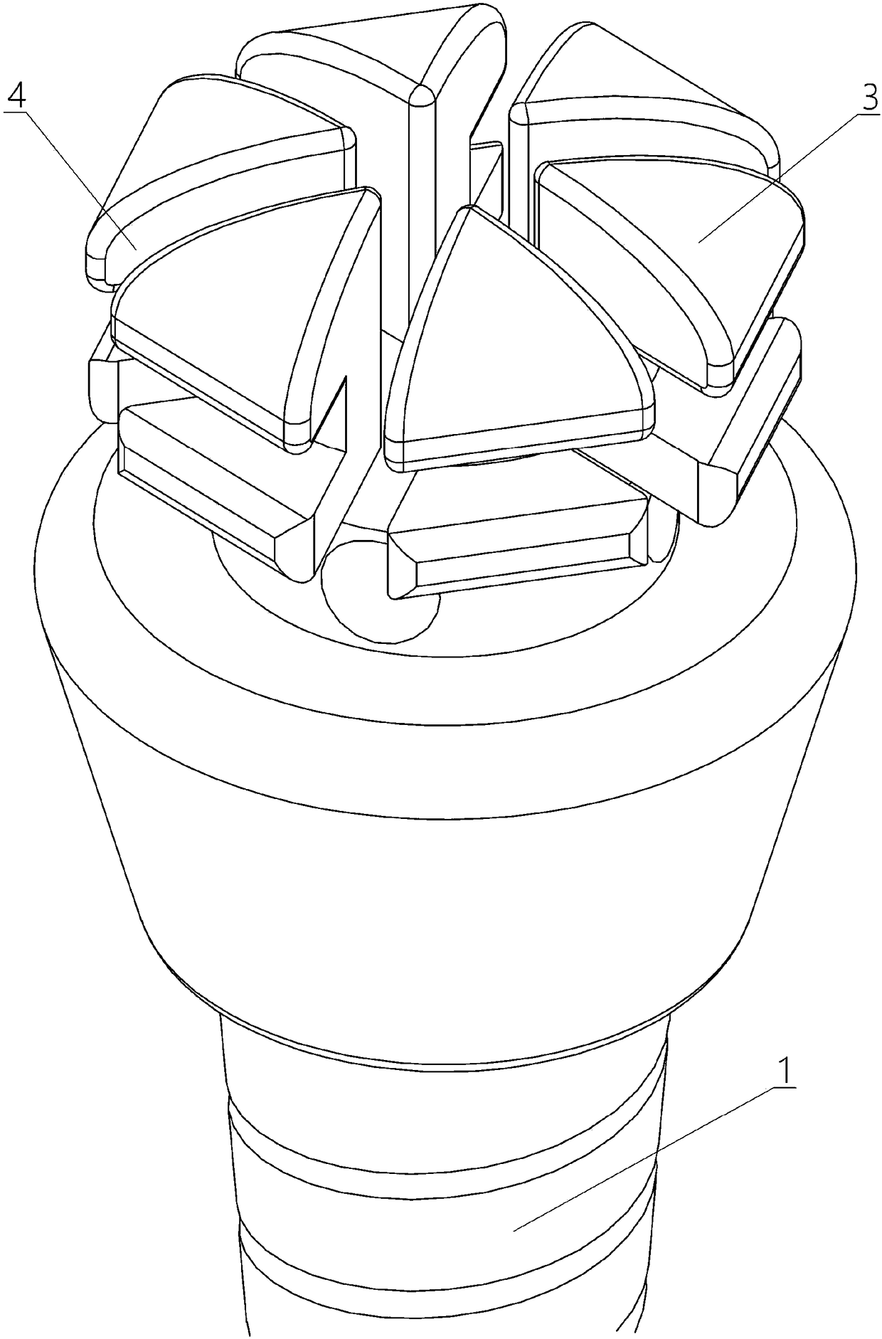
[0041] A first embodiment of the present invention provides a microscrew, see figure 1 As shown, it includes a head and a plug 1 connected to the head, and the plug 1 is used to implant and fix the microscrew in the patient's alveolar bone;
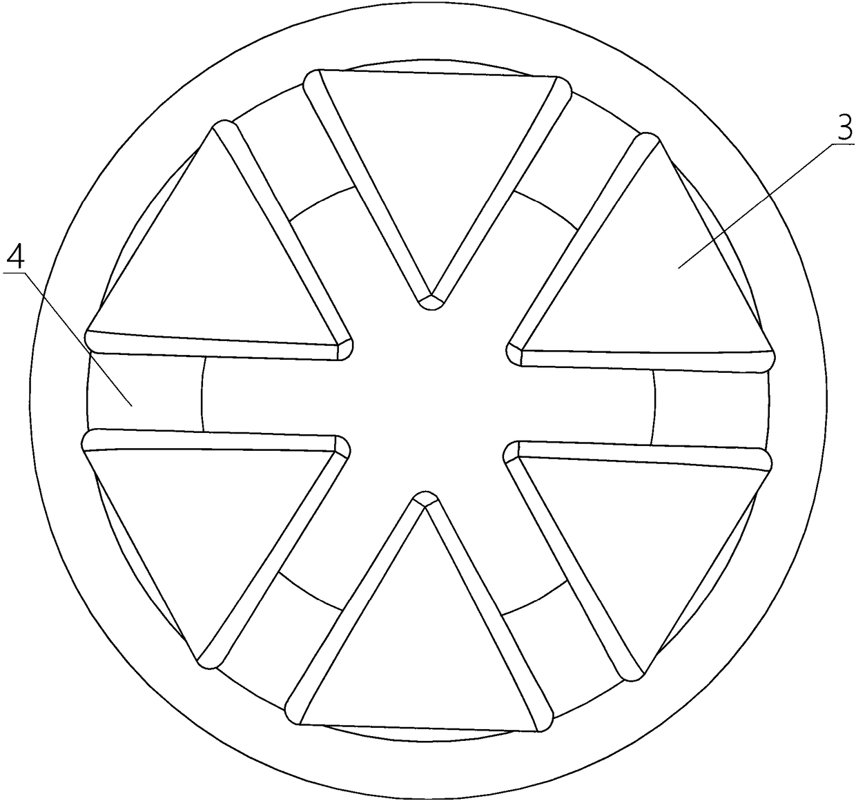
[0042] Wherein, the head includes a prism 3 with a regular N-sided cross-section, and M top grooves 4 are provided on the bottom surface of the prism 3 opposite to the pin 1, N is a natural number greater than or equal to 3, and M is greater than or equal to A natural number of 3, wherein the included angle between two adjacent top grooves 4 is less than 90 degrees.
[0043] Regarding the values of N and M, in this implementation manner, N may be 6, 8, 10, or 12, etc., and M is equal to N / 2.
[0044] Obviously, both for processing and for the connection with the screwdriver head, when N is an even number, it can be more convenient to design. The higher the number, the closer the head is to a round head, which makes it easier for the hea...
Embodiment approach 2
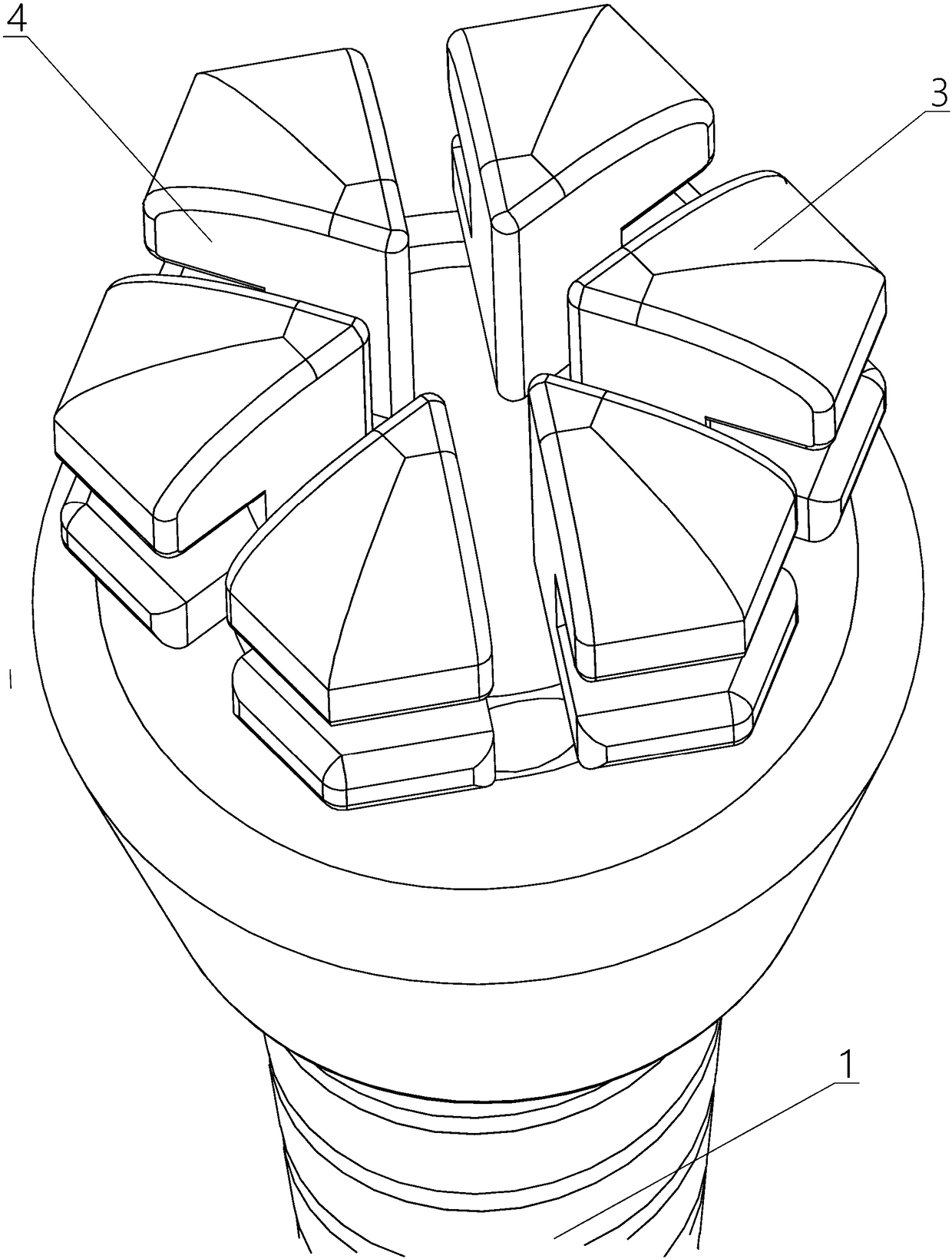
[0052] The second embodiment of the present invention provides a micro screw. The second embodiment is different from the first embodiment. The main difference is that, in the first embodiment of the present invention, the three top grooves 4 are The three adjacent vertices of the hexagonal prism form a penetration in the direction of the other three vertices corresponding to the three vertices; and in the second embodiment of the present invention, see image 3 As shown, the three top grooves 4 are respectively formed through the direction from the midpoints of the three adjacent sides of the bottom surface of the hexagonal prism to the midpoints of the other three sides corresponding to the three sides.
[0053] It can be seen from the figure that when the top groove 4 has a symmetrical structure, one of the two penetration modes of the first embodiment and the second embodiment can be selected.
[0054] Relatively speaking, in the second embodiment, the M top grooves 4 are ...
Embodiment approach 3
[0056] The third embodiment of the present invention provides a micro screw. The third embodiment is different from the first and second embodiments. The main difference is that in the first and second embodiments of the present invention, only The case where N is greater than or equal to 6 is illustrated, and in the third embodiment of the present invention, see Figure 4 As shown, the present invention will be described by taking N equal to 3 as an example.
[0057] Specifically, in this embodiment, N may be equal to M equal to 3;
[0058] The three top grooves 4 are respectively formed to penetrate from the three vertex angles of the triangular prism to the directions of the three faces corresponding to the three vertex angles.
[0059] When N is equal to 3, prism 3 is a triangular prism. When a triangular prism or a hexagonal prism is used, the tension spring of the triangular head can be used in conjunction with the head, which is very convenient as a supplementary choi...
PUM
 Abstract
Description
Claims
Application Information
 - R&D
- Intellectual Property
- Life Sciences
- Materials
- Tech Scout
- Unparalleled Data Quality
- Higher Quality Content
- 60% Fewer Hallucinations
Browse by: Latest US Patents, China's latest patents, Technical Efficacy Thesaurus, Application Domain, Technology Topic, Popular Technical Reports.
© 2025 PatSnap. All rights reserved.Legal|Privacy policy|Modern Slavery Act Transparency Statement|Sitemap|About US| Contact US: help@patsnap.com


