
Undercarriage structure of aerial helicopter model

A technology for helicopters and landing gear, applied in toy planes, entertainment, toys, etc., can solve the problems of poor applicability, lack of secondary auxiliary buffer, etc., and achieve good buffer protection effect

Inactive Publication Date: 2018-07-06
BINZHOU UNIV
View PDF2 Cites 1 Cited by
  • Summary
  • Abstract
  • Description
  • Claims
  • Application Information

AI Technical Summary

Problems solved by technology

[0007] In order to solve the above-mentioned technical problems, the present invention provides a landing gear structure of an aviation helicopter model aircraft, to solve the problem that most of the existing landing gears do not have the function of secondary auxiliary buffering in the process of actual use, and the buffering and shock-absorbing effect is effective. There is room for improvement, and most of them cannot adjust the cushioning and supporting strength according to the hardness of the ground and the weight of the model aircraft itself, resulting in poor applicability

Method used


Image

  • Undercarriage structure of aerial helicopter model
  • Undercarriage structure of aerial helicopter model
  • Undercarriage structure of aerial helicopter model

Examples


Embodiment

[0038] as attached figure 1 to attach Figure 8 Shown:

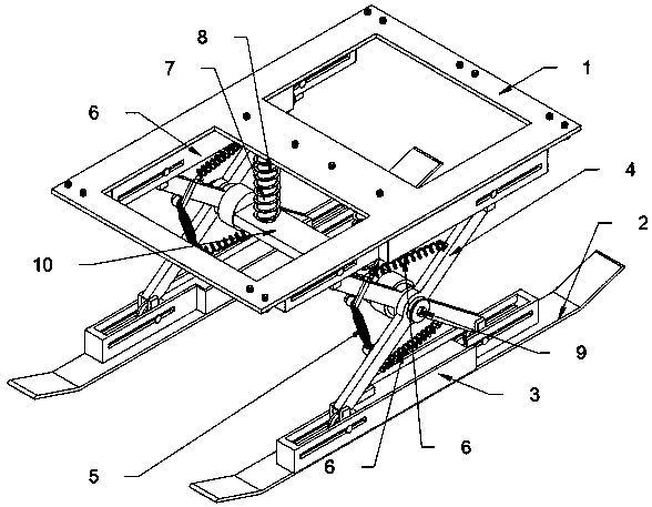
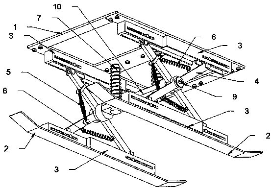
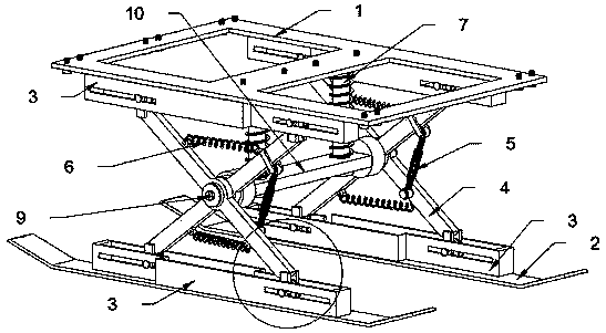
[0039] The invention provides a landing gear structure of an aviation helicopter model aircraft, which includes a locking positioning frame 1, a support plate 2, a positioning chute 3, a support rod 4, a gasket ring 401, a double-headed locking screw rod 5, and a tension spring 6. The sliding support shaft 7, the buffer spring 8, the locking limit plate 9, the main support plate 10 and the pulley 11, the locking and positioning frame 1 is arranged in a Japanese shape as a whole, and the bottom of the supporting plate is connected to the center by a symmetrical welding hanger. There are two sliding support shafts 7, and a positioning chute 3 is welded on the bottom of the left and right side plates; two circular mounting seats are welded symmetrically on the left and right sides of the main support plate 10, and the two places On the circular mounting seat, there is an insertion shaft that is welded to the outside; the ...


PUM


Abstract

The invention provides an undercarriage structure of an aerial helicopter model. The undercarriage structure comprises a spacer ring, double-end locking screws, a main support plate and pulleys; the position of the middle joint of each positioning chute is provided with a solid block, each of left and right sides of the solid block is provided with a rectangular track groove, and left-right arrangement positions of the rectangular track grooves and two X-like arranged support rods are laterally staggered with a certain distance; two slotting holes are formed in the main support plate symmetrically and penetratingly, two sliding support shafts are corresponding inserted in the slotting holes, and each sliding support shaft is sleeved with a buffer spring. By the arrangement of the four pulleys, the pulleys on the supporting rods can slide in a follow-up manner in the four rectangular track grooves formed in the two positioning chutes when the two supporting rods rotate with each other,and the supporting rods can be assured to rotate in the X-like manner and stretch and tighten the springs for normal shock buffering.

Description

technical field [0001] The invention belongs to the technical field of aircraft model landing gear, and more specifically relates to a landing gear structure of an aviation helicopter model aircraft. Background technique [0002] At present, the aeromodelling movement is booming on a large scale, and the aeromodelling technology is becoming more and more mature. However, the research and design of the landing gear of the model airplane helicopter as the parts outside the fuselage of the model airplane helicopter has also been put on the agenda. [0003] After retrieval, for example, the patent No. CN204093041U discloses a model airplane helicopter landing gear, which includes a base for connecting with the fuselage of the airplane model helicopter; a connecting rod group connected with the base, and the connecting rod group is provided with at least three, Each connecting rod group is connected with a shock-absorbing outrigger; and a power generating component is used to ge...

Claims


Application Information

Patent Timeline
IPC IPC(8): A63H27/133A63H27/32
CPCA63H27/02A63H27/12
Inventor 柳明
Owner BINZHOU UNIV
Learn More