Garbage pulverizing device

A lifting device and mounting plate technology, used in irradiation, grain processing, etc., can solve the problems of incomplete crushing, inconvenient handling, and low crushing efficiency.

Inactive Publication Date: 2018-07-06
赵坚
View PDF4 Cites 1 Cited by
  • Summary
  • Abstract
  • Description
  • Claims
  • Application Information

AI Technical Summary

Problems solved by technology

[0006] In order to overcome the shortcomings of inconvenient transportation, low crushing efficiency, and incomplete crushing, the technical problem to be solved by the present invention is to provide a preliminary crushing equipment for garbage recycling that is easy to carry, high crushing efficiency, and thorough crushing

Method used


Image

  • Garbage pulverizing device
  • Garbage pulverizing device
  • Garbage pulverizing device

Examples


Embodiment 1

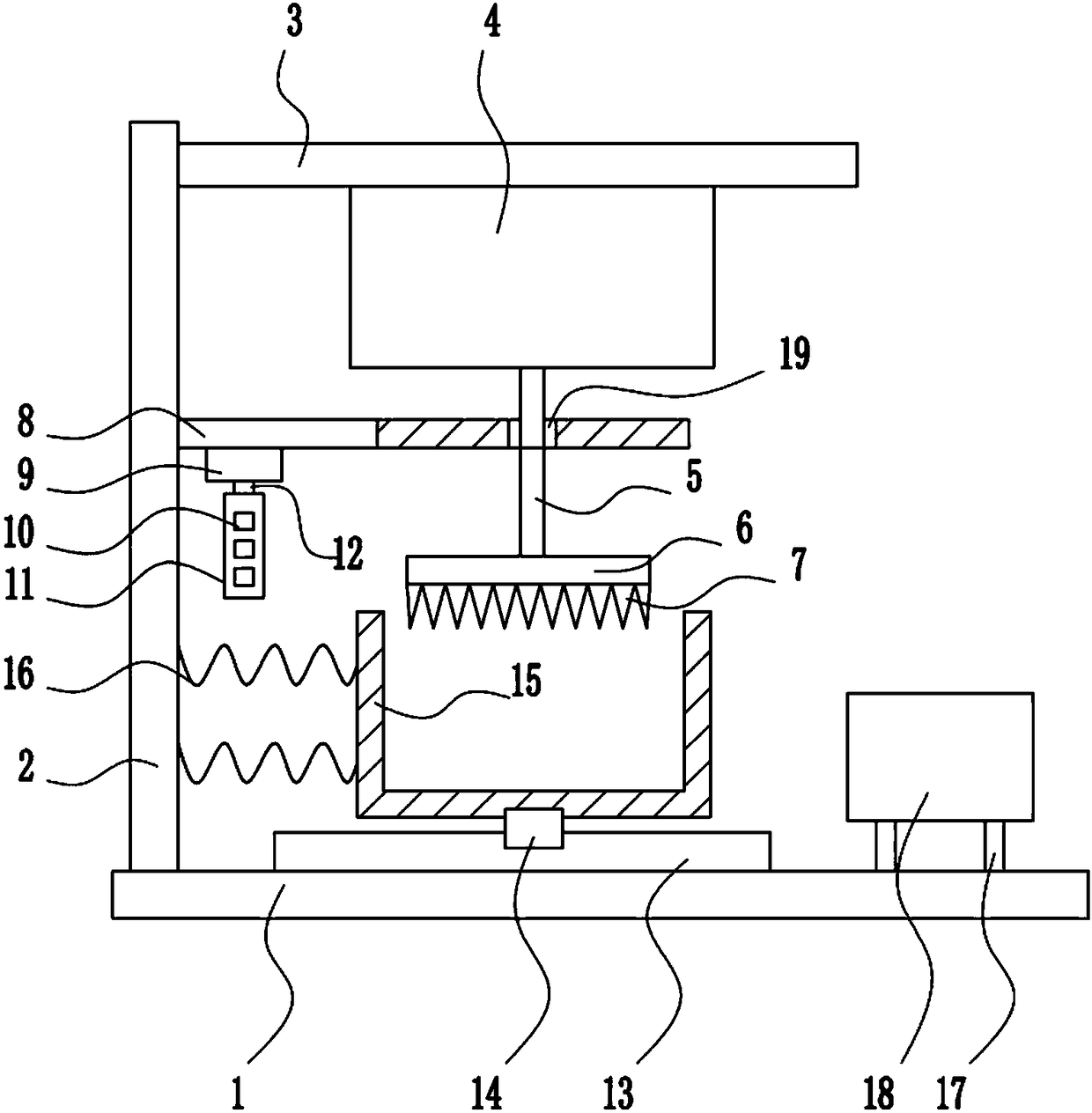
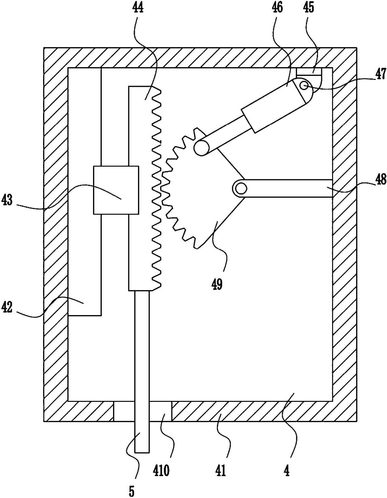
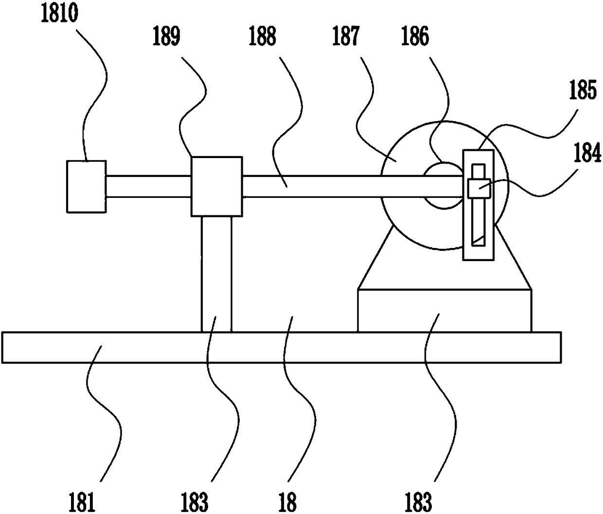
[0036] A garbage crushing device, such as Figure 1-5 As shown, it includes a bottom plate 1, a left frame 2, a top plate 3, a lifting device 4, a lifting rod 5, a pressing plate 6, a crushing tooth 7, a first mounting plate 8, a first motor 9, an ultraviolet lamp 10, a lamp stand 11, and A rotating shaft 12, a first slide rail 13, a first slider 14, a crushing frame 15, a spring 16, a first bracket 17 and a shaking device 18, a left frame 2 is welded on the left side of the top of the bottom plate 1, and a top plate is welded on the top of the left frame 2 3. There is a lifting device 4 in the middle of the bottom of the top plate 3, and a lifting rod 5 is connected to the bottom of the lifting device 4. A first mounting plate 8 is welded in the middle of the right side of the left frame 2, and a guide hole 19 is opened on the first mounting plate 8. The lifting rod 5 passes through the guide hole 19, the bottom end of the lifting rod 5 is welded with a pressure plate 6, the ...

Embodiment 2

[0038] A garbage crushing device, such as Figure 1-5 As shown, it includes a bottom plate 1, a left frame 2, a top plate 3, a lifting device 4, a lifting rod 5, a pressing plate 6, a crushing tooth 7, a first mounting plate 8, a first motor 9, an ultraviolet lamp 10, a lamp stand 11, and A rotating shaft 12, a first slide rail 13, a first slider 14, a crushing frame 15, a spring 16, a first bracket 17 and a shaking device 18, a left frame 2 is welded on the left side of the top of the bottom plate 1, and a top plate is welded on the top of the left frame 2 3. There is a lifting device 4 in the middle of the bottom of the top plate 3, and a lifting rod 5 is connected to the bottom of the lifting device 4. A first mounting plate 8 is welded in the middle of the right side of the left frame 2, and a guide hole 19 is opened on the first mounting plate 8. The lifting rod 5 passes through the guide hole 19, the bottom end of the lifting rod 5 is welded with a pressure plate 6, the ...

Embodiment 3

[0041] A garbage crushing device, such as Figure 1-5 As shown, it includes a bottom plate 1, a left frame 2, a top plate 3, a lifting device 4, a lifting rod 5, a pressing plate 6, a crushing tooth 7, a first mounting plate 8, a first motor 9, an ultraviolet lamp 10, a lamp stand 11, and A rotating shaft 12, a first slide rail 13, a first slider 14, a crushing frame 15, a spring 16, a first bracket 17 and a shaking device 18, a left frame 2 is welded on the left side of the top of the bottom plate 1, and a top plate is welded on the top of the left frame 2 3. There is a lifting device 4 in the middle of the bottom of the top plate 3, and a lifting rod 5 is connected to the bottom of the lifting device 4. A first mounting plate 8 is welded in the middle of the right side of the left frame 2, and a guide hole 19 is opened on the first mounting plate 8. The lifting rod 5 passes through the guide hole 19, the bottom end of the lifting rod 5 is welded with a pressure plate 6, the ...


PUM


Abstract

The invention relates to pulverizing equipment, in particular to a garbage pulverizing device, and aims at achieving the technical purpose of providing garbage recycling preliminary pulverizing equipment convenient to carry, high in pulverizing efficiency and thorough in pulverizing. To achieve the above technical purpose, the garbage pulverizing device is provided and comprises a bottom plate, aleft frame, a top plate, a lifting device, a lifting rod, a pressing plate, pulverizing teeth, a first installing plate, a first motor, an ultraviolet lamp, a lamp frame, a first rotation shaft and the like. The left frame is welded to the left side of the top of the bottom plate. The top plate is welded to the top end of the left frame. The lifting device is arranged in the middle of the bottom of the top plate. The bottom of the lifting device is connected with the lifting rod. Through control over stretching and shortening of an electric push rod, a connecting rod is made to drive the lifting rod to move up and down, the lifting rod drives the pulverizing teeth at the lower end of the lifting rod to constantly move up and down, and the purpose of garbage pulverizing is achieved.

Description

technical field [0001] The invention relates to a crushing device, in particular to a garbage crushing device. Background technique [0002] Garbage refers to unwanted or useless solid and fluid substances. In densely populated cities, garbage disposal is a headache. Common way is to send to landfill after collecting for landfill treatment, or burn with incinerator. But both create environmental concerns, and ending overconsumption could further reduce landfill saturation. Waste disposal in landfills not only pollutes the groundwater and emits a bad smell, but many cities have less and less landfill area. Incineration inevitably produces toxic gases that harm living organisms. Most cities are researching ways to reduce waste and encourage recycling. [0003] Recycling refers to the physical or mechanical processing of useful substances separated from waste into reused products. [0004] People's lives are becoming more and more diversified, and the garbage produced is ...

Claims


Application Information

Patent Timeline
Patent Type & Authority Applications(China)
IPC IPC(8): B02C1/14B02C23/00A61L2/10
CPCB02C1/14A61L2/10B02C23/00B02C2201/06
Inventor 不公告发明人
Owner 赵坚
Why Eureka
Try Eureka