Supercharge Your Innovation With Domain-Expert AI Agents!

Range hood with smoke deflectors and control method thereof

A range hood and control method technology, applied in the direction of oil fume removal, heating method, household heating, etc., can solve the problems of large energy loss, long distance, escape of oil fume gas, etc., and achieve the effect of strengthening

Pending Publication Date: 2018-07-06
NINGBO FOTILE KITCHEN WARE CO LTD
View PDF9 Cites 11 Cited by
  • Summary
  • Abstract
  • Description
  • Claims
  • Application Information

AI Technical Summary

Problems solved by technology

[0004] The above-mentioned range hood adopts a single smoke guide plate at the smoke collection cavity to turn the negative pressure area from the center to the surrounding. When cooking with a single stove, the amount of oil smoke is generated in a large amount on one side and rises rapidly. Under the influence of the wall attachment of the smoke deflector, the oil fume enters the suction port of the range hood from all sides. Because the distance traveled by the oil fume from one side to the other is too long, the energy loss is large, and when the amount of oil fume is too large, some Fume gas is prone to escape

Method used


Image

  • Range hood with smoke deflectors and control method thereof
  • Range hood with smoke deflectors and control method thereof
  • Range hood with smoke deflectors and control method thereof

Examples


Embodiment 1

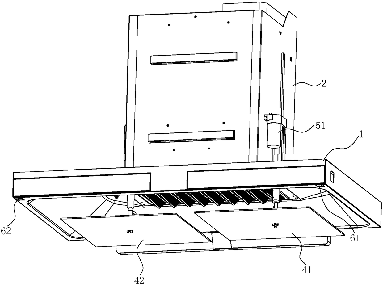
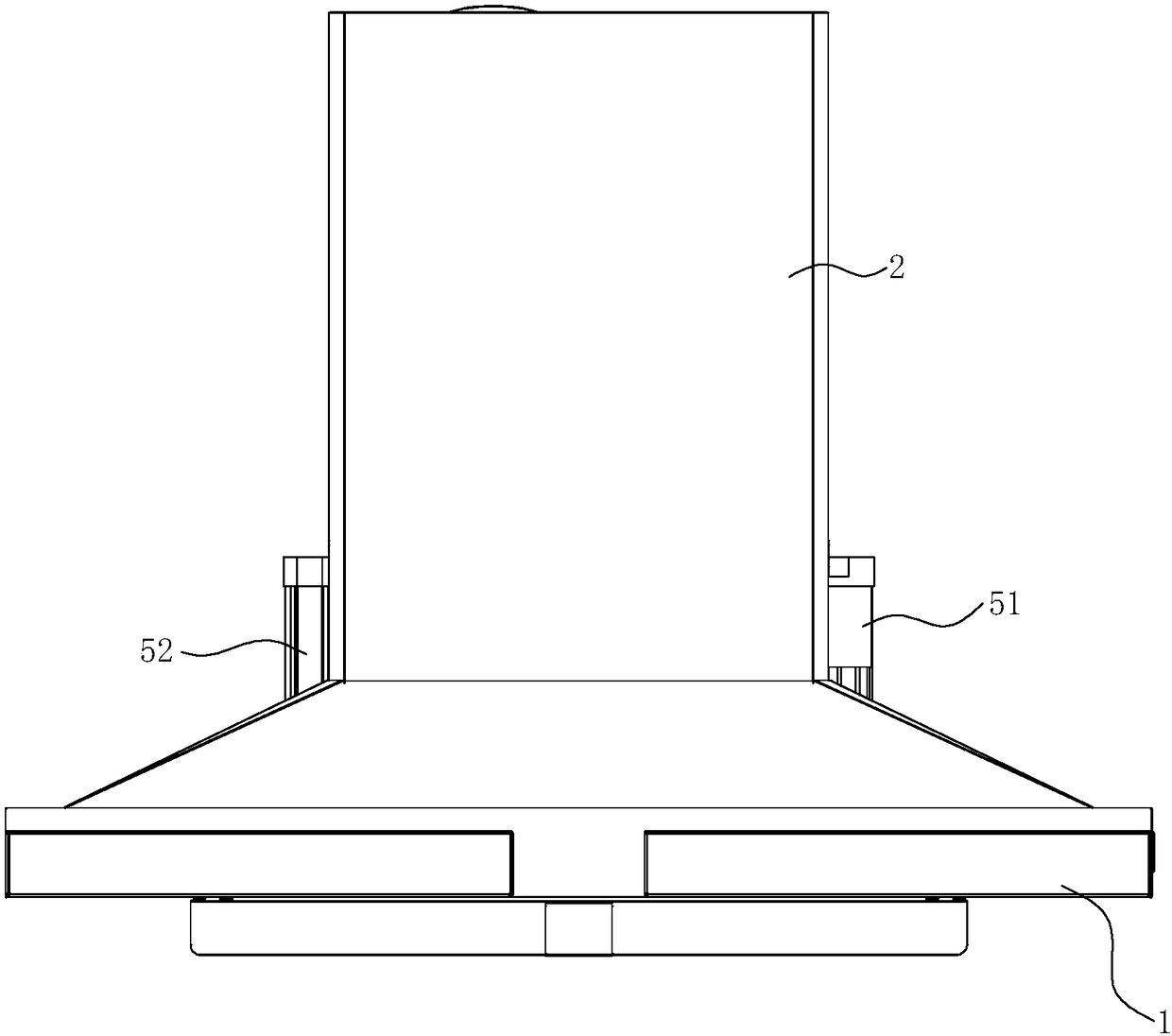
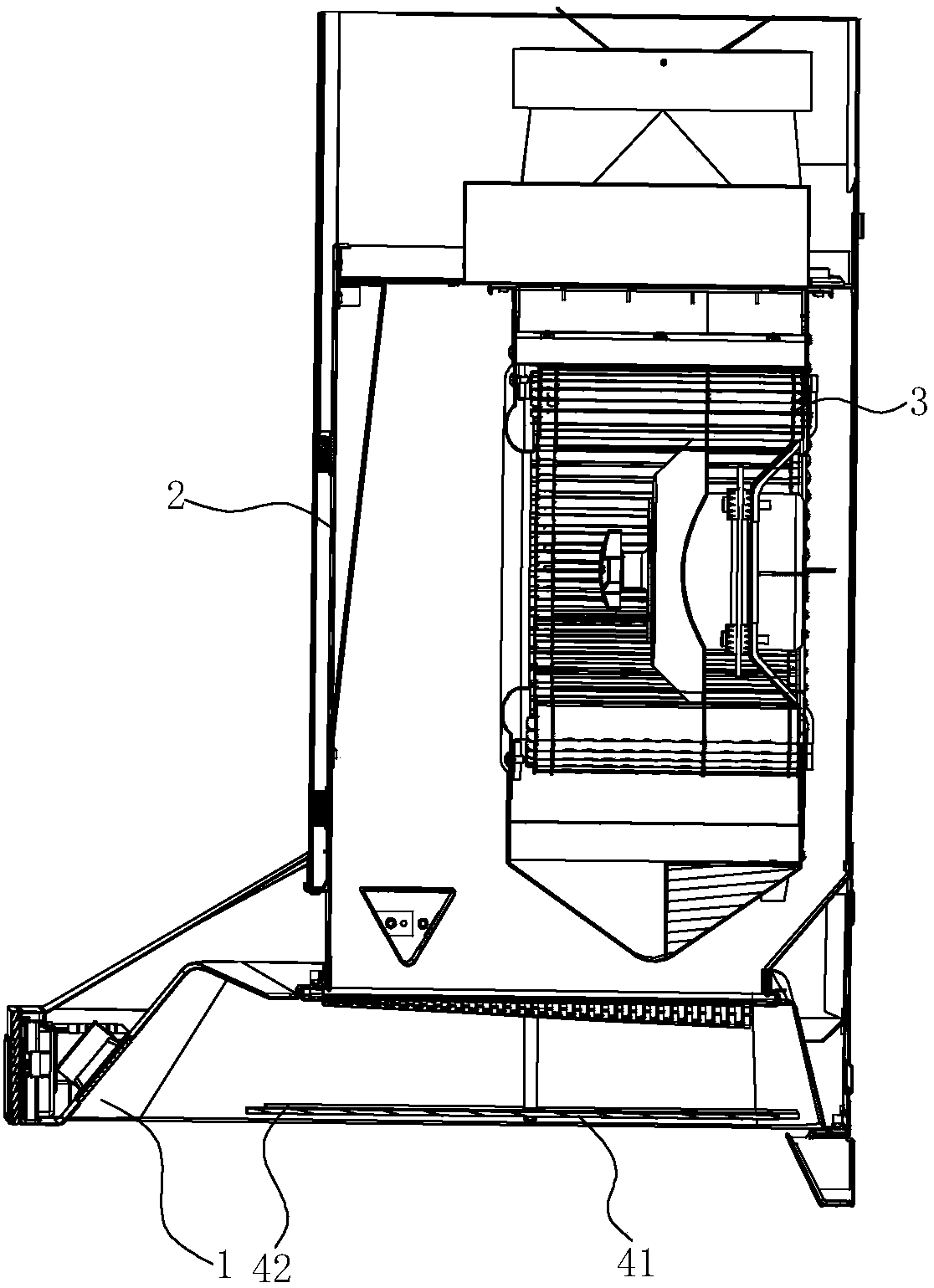
[0032] see Figure 1 ~ Figure 3 , a range hood with a smoke deflector, comprising a smoke collection hood 1, a fan cover 2 arranged above the smoke collection hood 1, and a fan 3 is arranged in the fan cover 2.

[0033] An air inlet 11 is provided on the smoke collecting hood 1, and a smoke guide plate is arranged below the air inlet 11. In this embodiment, the smoke guide plate includes a first smoke guide plate 41 and a second smoke guide plate 42, two smoke guide plates They are respectively arranged on both sides below the air inlet 11, so as to be compatible with a stove with double burners. The first smoke guide plate 41 is provided with a first driving mechanism 51, and the second smoke guide plate 42 is provided with a second drive mechanism 52, so that the first smoke guide plate 41 and the second smoke guide plate 42 can be independently driven up and down. . In this embodiment, both the first drive mechanism 51 and the second drive mechanism 52 are electric push r...

Embodiment 2

[0043] see Figure 8 and Figure 9 , the difference from the first embodiment above is that in this embodiment, the drive mechanism including the first drive mechanism 51 and the second drive mechanism 52 is used to drive the first smoke guide plate 41 and the second smoke guide plate 42 respectively. rotate.

[0044] The first driving mechanism 51 includes a first motor 511 and a first rotating shaft 512, the first motor 511 is arranged on the rear side of the smoke collecting hood 1, one end of the first rotating shaft 512 is connected with the output shaft of the first motor 511, and the other end rotates The first smoke guide plate 41 is connected to the first rotating shaft 512, and can be fixed by welding, for example. Correspondingly, the second drive mechanism 52 includes a second motor 521 and a second rotating shaft 522, the second motor 521 is arranged on the rear side of the smoke collecting hood 1, one end of the second rotating shaft 522 is connected with the o...


PUM


Abstract

The invention discloses a range hood with smoke deflectors. The range hood comprises an exhaust fume collecting hood body, an air inlet is formed in the exhaust fume collecting hood body, and the deflectors are arranged at the lower part of the air inlet. The range hood is characterized in that the smoke deflectors comprise a first smoke deflector and a second smoke deflector which are arranged onthe two sides of the lower part of the air inlet. The invention further discloses a control method for the range hood. According to the range hood and the control method thereof, the double-smoke-deflector structure is adopted, so that a negative pressure area can be expanded outwards, meanwhile, a center negative pressure area can be reinforced, and the multi-sided air inlet effect is achieved;in addition, the cooking condition of a kitchen is pre-judged through monitoring of a temperature sensor, and therefore by means of automatic control, lifting of the smoke deflectors on the two sidescan be adjusted in real time, and the cooking fume suction effect is enhanced.

Description

technical field [0001] The invention relates to a range hood, in particular to a range hood with a smoke guide plate, and a control method for the range hood. Background technique [0002] At present, the overall installation height of the European-style range hood determines that the range hood is relatively far away from the pan that produces the oil fume, and the negative pressure loss is relatively large. In order to improve the range hood effect of the range hood, people have improved the structure of the range hood, and the usual method is to improve the fan system of the range hood, such as increasing the power of the fan, such as improving the structure of the impeller, etc. Wait. Although this improvement can effectively improve the range hood's range hood effect, it needs to improve the structure of the entire fan system, which is not only more complicated, but also cannot improve the distribution of the negative pressure area when the range hood is working, and t...

Claims


Application Information

Patent Timeline
Patent Type & Authority Applications(China)
IPC IPC(8): F24C15/20
CPCF24C15/20F24C15/2021
Inventor 黄友根何立博李志峰陈浩辉边乐超茅忠群诸永定李斌
Owner NINGBO FOTILE KITCHEN WARE CO LTD
Features
  • R&D
  • Intellectual Property
  • Life Sciences
  • Materials
  • Tech Scout
  • Unparalleled Data Quality
  • Higher Quality Content
  • 60% Fewer Hallucinations
Learn More