Connector, adapter and quick-plug optic fiber connection component

An optical fiber connection and connector technology, applied in the field of optical distribution network, can solve the problem of small pull-out force, and achieve the effect of small pull-out force, large locking force and small insertion force

Pending Publication Date: 2018-07-06
FENGHUO COMM SCI & TECH CO LTD
View PDF7 Cites 21 Cited by
  • Summary
  • Abstract
  • Description
  • Claims
  • Application Information

AI Technical Summary

Problems solved by technology

[0007] In view of the defects existing in the prior art, the purpose of the present invention is to provide a quick plug-in optical fiber connection assembly to solve the problem of small pull-off force

Method used


Image

  • Connector, adapter and quick-plug optic fiber connection component
  • Connector, adapter and quick-plug optic fiber connection component
  • Connector, adapter and quick-plug optic fiber connection component

Examples


Embodiment 1

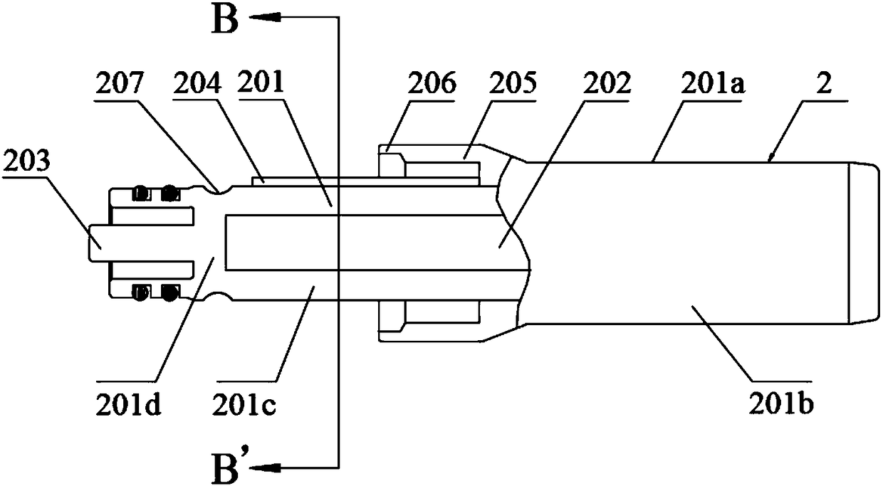
[0105] Please also refer to Figure 1 to Figure 19 , the embodiment of the present invention provides a connector 2, which is used for optical fiber connection, and the connector 2 includes a plug body 201, and the plug body 201 is used for carrying an optical cable 215 and for hand-held operation. The outside of the plug body 201 is provided with a plug housing 205, and the front end of the plug housing 205 has a pushing device 206; the outer surface of the plug body 201 is provided with a groove for engaging with an adapter matching the connector. The groove may be an annular groove 207 . Compared with the connection method using threads in the prior art, the use of grooves as the connection structure can withstand greater pull-off force, and does not need to be rotated, can be inserted directly, and is easy to operate. And since there is no need to rotate, the space required for hand operation is small, which can increase the density of the connector on the panel.

Embodiment 2

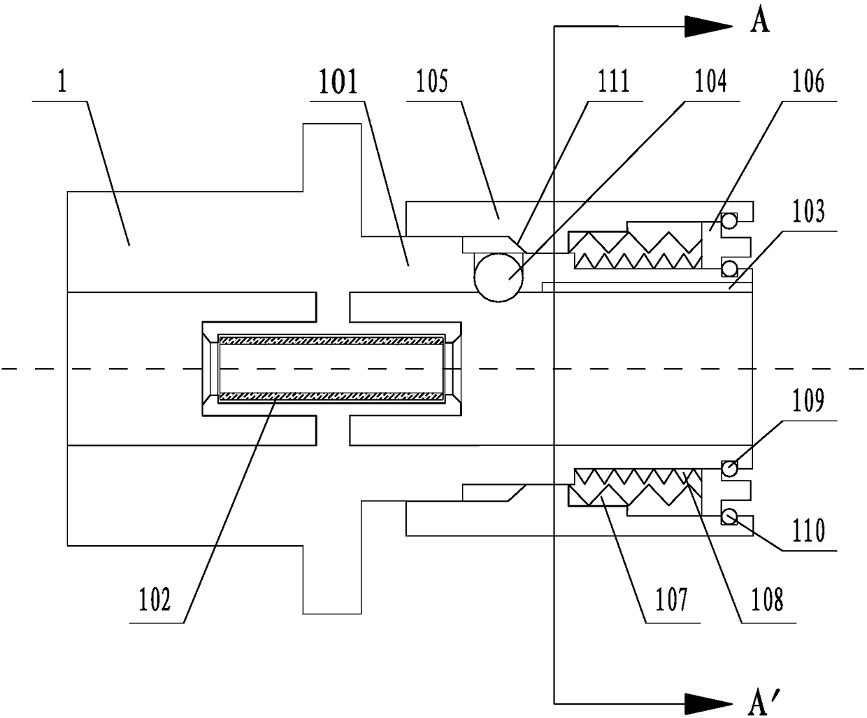
[0107] Please also refer to Figure 1 to Figure 19 , as an optional embodiment, the difference between this embodiment and Embodiment 1 is that: the pushing device 206 is used to push the inner sleeve 106 of the adapter 1 adapted to the connector 2 . To make adapter 1 change state to connect with connector. Of course, the ejecting device 206 can also eject other similar structures of the adapter 1, as long as it can change the state of the adapter 1 and achieve the effect of connection.

Embodiment 3

[0109] Please also refer to Figure 1 to Figure 19 , as an optional embodiment, the difference between this embodiment and Embodiment 1 is that the ejecting device 206 is an ejecting block formed by extending from the outer surface of the plug body 201 . If the ejector device 206 adopts this structure, then the inner sleeve 106 matched with the ejector device 206 can be provided with a protrusion protruding from the outer sleeve 205 (not shown), so that the ejector device 206 can push the inner sleeve 106 And move axially relative to the outer sleeve 205 .


PUM


Abstract

The invention relates to the field of optical distribution networks and discloses a quick-plug optic fiber connection component. The optic fiber connection component comprises an adapter and a connector, one end of an adapter body is provided with a locking structure, and the locking structure comprises a positioning limiting groove, a steel ball, an outer sleeve and an inner sleeve. A plug body of the connector is provided with a positioning limiting projection fitting the positioning limiting groove, the plug body is externally provided with a plug outer sleeve, a pushing device for pushingthe inner sleeve is arranged at the front end of the plug outer sleeve, the outer surface of the plug body is peripherally provided with an annular groove fitting the steel ball, and the adapter and the connector can be locked when the steel ball is pressed into the annular groove and clamped tightly by a slope of the outer sleeve of the adapter. By the optic fiber connection component, convenience and quickness in plugging and unplugging of the adapter and the connector can be achieved, locking reliability is realized, and problems of locking force insufficiency and inconvenience in pluggingand unplugging of an existing optic fiber connection component are effectively solved.

Description

technical field [0001] The invention relates to the field of optical distribution network, in particular to a connector, an adapter and a quick-plug optical fiber connection assembly. Background technique [0002] With the large-scale deployment of FTTH (Fiber To The Home, fiber to the home), optical fiber connection components are increasingly widely used. Generally, fiber optic connection assemblies include fiber optic connectors and adapters. Most of the fiber optic connectors and adapters used at this stage are industry standard connectors and adapters. This type of connector and adapter is designed to solve the problem of optical fiber connection indoors or in a protective box (box), so there are the following defects in actual use: [0003] 1. The existing standard connectors and adapters have a small pull-off force, which cannot meet the connection of the optical fiber under high tension. Therefore, it is generally necessary to use throat clamps, clamps, etc. to add...

Claims


Application Information

Patent Timeline
Patent Type & Authority Applications(China)
IPC IPC(8): G02B6/38
CPCG02B6/3807G02B6/3821G02B6/3825G02B6/3831G02B6/3847G02B6/3849G02B6/3869G02B6/3881G02B6/3887G02B6/3891G02B6/3816
Inventor 黄美金邹峰魏文振朱丽丽
Owner FENGHUO COMM SCI & TECH CO LTD
Why Eureka
Try Eureka