Catadioptric optical system and image pickup apparatus

A technology of optical systems and camera devices, applied in optics, optical components, instruments, etc., can solve the problems of limited magnification range, image quality degradation, and difficulty in total lens length, etc., and achieve excellent imaging performance

Active Publication Date: 2018-07-06
TAMRON +1
View PDF7 Cites 21 Cited by
  • Summary
  • Abstract
  • Description
  • Claims
  • Application Information

AI Technical Summary

Problems solved by technology

This digital zoom lens is a function that eliminates the need to physically move components like an optical zoom lens, but if the image is enlarged too much, the image quality will deteriorate
Due to this image degradation, there is a limit to the range that can be zoomed in with digital zoom
[0011] On the other hand, the reality is that it is very difficult to form an optical zoom lens with a desired zoom ratio to a desired total lens length

Method used


Image

  • Catadioptric optical system and image pickup apparatus
  • Catadioptric optical system and image pickup apparatus
  • Catadioptric optical system and image pickup apparatus

Examples


no. 1 example

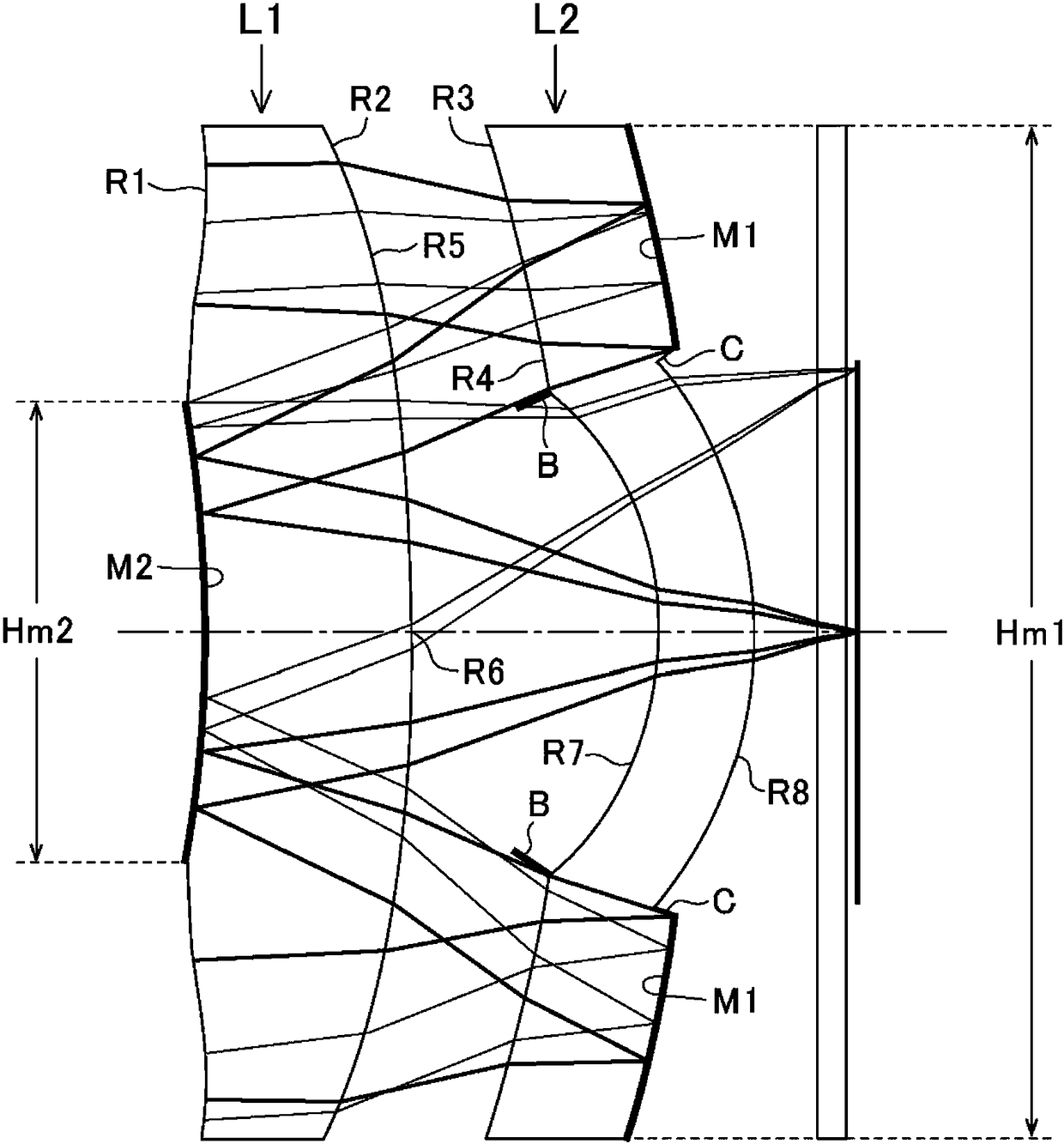
[0137] Such as figure 1 As shown, the structure of the catadioptric optical system of the first embodiment has a first lens L1 and a second lens L2.

[0138] The first lens L1 has a refraction surface R1 (first refraction surface) in the peripheral area of ​​the object side surface, and has a second reflection surface M2 in the central area of ​​the object side surface of the first lens L1. In addition, the first lens L1 has a refractive surface R2 in the peripheral area of ​​the imaging side surface, and has a refractive surface R5 and a refractive surface R6 in the central area of ​​the imaging side surface of the first lens L1.

[0139] The second lens L2 has a refractive surface R3 in the peripheral area of ​​the object-side surface, and has a refractive surface R4 and a refractive surface R7 in the central area of ​​the object-side surface of the second lens L2. In addition, the second lens L2 has a first reflective surface M1 in the peripheral region of the image-side ...

no. 2 example

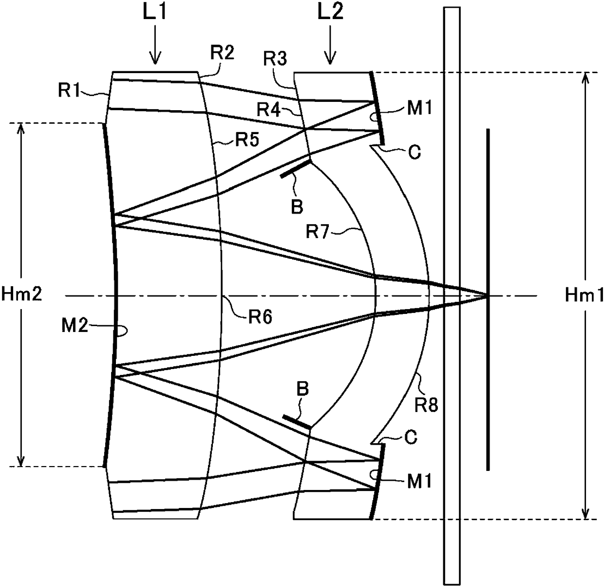
[0148] Such as image 3 As shown, the structure of the catadioptric optical system of the second embodiment has a first lens L1 and a second lens L2.

[0149] The first lens L1 has a refraction surface R1 (first refraction surface) in the peripheral area of ​​the object side surface, and has a second reflection surface M2 in the central area of ​​the object side surface of the first lens L1. In addition, the first lens L1 has a refractive surface R2 in the peripheral area of ​​the imaging side surface, and has a refractive surface R5 and a refractive surface R6 in the central area of ​​the imaging side surface of the first lens L1.

[0150] There is a refraction surface R3 in the peripheral area of ​​the object side surface of the second lens L2, and there are refraction surfaces R4 and R7 in the center area of ​​the object side surface of the second lens L2, and, in the second lens L2 The peripheral area of ​​the image-side surface has a first reflective surface M1, and the ...

no. 3 example

[0159] Such as Figure 5 As shown, the structure of the catadioptric optical system of the third embodiment has a first lens L1 and a second lens L2.

[0160] The first lens L1 has a refraction surface R1 (first refraction surface) in the peripheral area of ​​the object side surface, and has a second reflection surface M2 in the central area of ​​the object side surface of the first lens L1. In addition, the first lens L1 has a refractive surface R2 in the peripheral area of ​​the imaging side surface, and has a refractive surface R5 and a refractive surface R6 in the central area of ​​the imaging side surface of the first lens L1.

[0161] The second lens L2 has a refractive surface R3 in the peripheral area of ​​the object-side surface, and has a refractive surface R4 and a refractive surface R7 in the central area of ​​the object-side surface of the second lens L2. In addition, the second lens L2 has a first reflective surface M1 in the peripheral region of the image-side ...


PUM


Abstract

The present invention provides a catadioptric optical system and an image pickup apparatus. A thin catadioptric optical system having a prescribed imaging performance, and a bright and long focal length with a small low back factor is provided. A catadioptric optical system and an imaging pickup device including the catadioptric optical system are provided. The catadioptric optical system is a coaxial birefringent optical system, and has a first lens and a second lens which are arranged at an air interval from an object side; a first refractive surface is formed in a peripheral region of a surface on the object side of the first lens; a second reflecting surface is formed in a central region of the surface on the object side of the first lens; a first reflecting surface is formed in the peripheral region of a surface on an imaging side of the second lens; the second refractive surface is formed in a central region of the surface on the imaging side of the second lens; and predeterminedconditions related to the effective diameters of the first reflecting surface and the second reflecting surface are satisfied.

Description

technical field [0001] The present invention relates to a catadioptric optical system and an imaging device, and more specifically relates to an imaging device that is bright and thin in the direction of the optical axis and that can be properly mounted on a mobile phone, a mobile device, a robot, an in-vehicle device, etc. A thin catadioptric optical system and an imaging device equipped with the catadioptric optical system. Background technique [0002] Conventionally, in order to reduce the protruding amount of the imaging system of a mobile phone from its approximate thickness, etc., in the field of various devices, it is desired to be thin in the optical axis direction, that is, from the first surface of the lens on the subject side to the imaging position. Thin catadioptric optical system with short "total lens length" of the distance on the optical axis. [0003] As a conventional thin catadioptric optical system, such as Figure 14 As shown, an optical system is pro...

Claims


Application Information

Patent Timeline
Patent Type & Authority Applications(China)
IPC IPC(8): G02B13/00G02B17/08
CPCG02B13/003G02B13/0065G02B17/0808G02B17/086
Inventor 佐藤拙平川纯田中幸夫水上雅文
Owner TAMRON
Why Eureka
Try Eureka