Catadioptric optical system and camera device
A technology of optical systems and camera devices, applied in optics, optical components, instruments, etc., can solve the problems of limited magnification range, reduced image quality, difficult total lens length, etc., and achieve the effect of excellent imaging performance
- Summary
- Abstract
- Description
- Claims
- Application Information
AI Technical Summary
Problems solved by technology
Method used
Image
Examples
no. 1 example
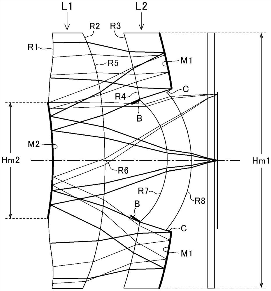
[0137] like figure 1 As shown, the structure of the catadioptric optical system of the first embodiment has a first lens L1 and a second lens L2.
[0138] The first lens L1 has a refraction surface R1 (first refraction surface) in the peripheral area of the object side surface, and has a second reflection surface M2 in the central area of the object side surface of the first lens L1. In addition, the first lens L1 has a refractive surface R2 in the peripheral area of the imaging side surface, and has a refractive surface R5 and a refractive surface R6 in the central area of the imaging side surface of the first lens L1.
[0139] The peripheral area of the object-side surface of second lens L2 has a refractive surface R3, and the central area of the object-side surface of second lens L2 has a refractive surface R4 and a refractive surface R7. In addition, the second lens L2 has a first reflective surface M1 in the peripheral region of the image-side surface, and h...
no. 2 example
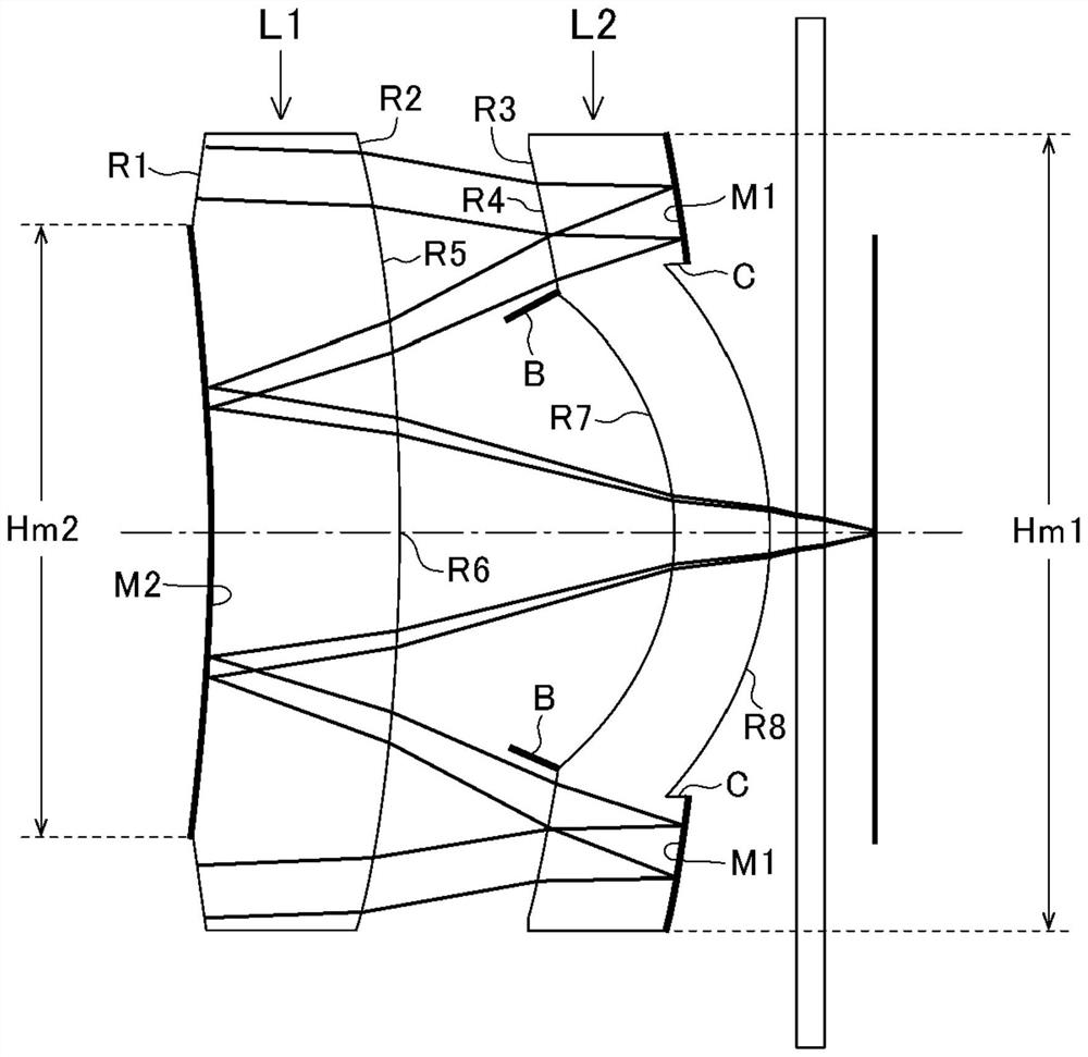
[0148] like image 3 As shown, the structure of the catadioptric optical system of the second embodiment has a first lens L1 and a second lens L2.
[0149] The first lens L1 has a refraction surface R1 (first refraction surface) in the peripheral area of the object side surface, and has a second reflection surface M2 in the central area of the object side surface of the first lens L1. In addition, the first lens L1 has a refractive surface R2 in the peripheral area of the imaging side surface, and has a refractive surface R5 and a refractive surface R6 in the central area of the imaging side surface of the first lens L1.
[0150] There is a refraction surface R3 in the peripheral area of the object side surface of the second lens L2, and there are refraction surfaces R4 and R7 in the center area of the object side surface of the second lens L2, and, in the second lens L2 The peripheral area of the image-side surface has a first reflective surface M1, and the cen...
no. 3 example
[0159] like Figure 5 As shown, the structure of the catadioptric optical system of the third embodiment has a first lens L1 and a second lens L2.
[0160] The first lens L1 has a refraction surface R1 (first refraction surface) in the peripheral area of the object side surface, and has a second reflection surface M2 in the central area of the object side surface of the first lens L1. In addition, the first lens L1 has a refractive surface R2 in the peripheral area of the imaging side surface, and has a refractive surface R5 and a refractive surface R6 in the central area of the imaging side surface of the first lens L1.
[0161] The second lens L2 has a refractive surface R3 in the peripheral area of the object-side surface, and has a refractive surface R4 and a refractive surface R7 in the central area of the object-side surface of the second lens L2. In addition, the second lens L2 has a first reflective surface M1 in the peripheral region of the image-side sur...
PUM
 Abstract
Description
Claims
Application Information
 - R&D
- Intellectual Property
- Life Sciences
- Materials
- Tech Scout
- Unparalleled Data Quality
- Higher Quality Content
- 60% Fewer Hallucinations
Browse by: Latest US Patents, China's latest patents, Technical Efficacy Thesaurus, Application Domain, Technology Topic, Popular Technical Reports.
© 2025 PatSnap. All rights reserved.Legal|Privacy policy|Modern Slavery Act Transparency Statement|Sitemap|About US| Contact US: help@patsnap.com


