Projection system

A technology of projection system and spokes, which is applied in the field of projection systems, can solve problems such as the effect of spokes affecting the quality of projected images, and achieve the effect of improving the quality of projected images

Active Publication Date: 2018-07-06
APPOTRONICS CORP LTD
View PDF6 Cites 8 Cited by
  • Summary
  • Abstract
  • Description
  • Claims
  • Application Information

AI Technical Summary

Problems solved by technology

[0004] In order to solve the technical problem that the spoke effect affects the projected image quality in the prior art, the prese

Method used


Image

  • Projection system
  • Projection system
  • Projection system

Examples


no. 1 approach

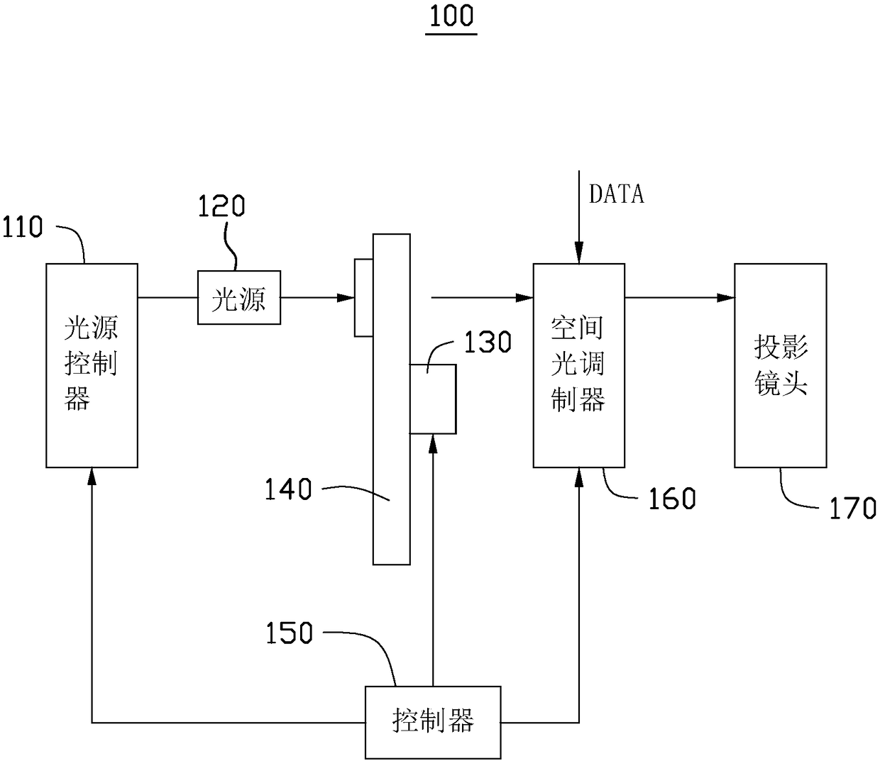
[0049] see figure 1 , figure 1 is a schematic structural diagram of the projection system 100 according to the first embodiment of the present invention. The projection system 100 includes a light source controller 110 , a light source 120 , a color wheel driving device 130 , a color wheel 140 , a controller 150 , a spatial light modulator 160 , and a projection lens 170 . The light source controller 110 is used to drive the light source 120 to emit light, the color wheel driving device 130 is used to drive the color wheel 140 to move, and the color wheel 140 is used to receive the light emitted by the light source 120 and emit at least Two colors of light, the spatial light modulator 160 is used to perform image modulation on the at least two colors of light according to the image data DATA to generate image light, and the projection lens 170 is used to project according to the image light to display projected image. The controller 150 is used to control the light source c...

no. 2 approach

[0071] see Figure 7 , Figure 7 It is a schematic diagram of the driving sequence of the light source and the spatial light modulator of the projection system according to the second embodiment of the present invention. The projection system of the second embodiment is basically the same as the projection system of the first embodiment, that is to say, the description of the projection system of the first embodiment can also basically be used for the projection of the second embodiment The main difference between the two systems is that the driving timing of the light source is different. Specifically, in the second implementation manner, the spatial light modulator is turned off during the spoke period T2 but the light source is still turned on during the spoke period T2.

[0072] In the second embodiment, only the spatial light modulator is turned off during the spoke period T2. Such control changes the image display quality in the simplest way.

no. 3 approach

[0074] see Figure 8 , Figure 8 It is a schematic diagram of the driving sequence of the light source and the spatial light modulator of the projection system according to the third embodiment of the present invention. The projection system of the third embodiment is basically the same as the projection system of the first embodiment, that is to say, the description of the projection system of the first embodiment can also basically be used for the projection of the third embodiment The main difference between the two systems is that the driving timing of the light source is different. Specifically, in the third embodiment, the light source enters the off-process period t2 in the non-spoke period T1 before the start of the spoke period T2, and enters the on-process period t1 at the beginning of the next non-spoke period T1. Specifically, such as Figure 7 As shown, the light source enters the turn-on period t1, the full turn-on period t3 and the turn-off period t2 in seque...


PUM


Abstract

The present invention relates to a projection system. The projection system comprises a light source, a color wheel and a spatial light modulator. The light source is configured to emit light of the light source; the color wheel is located on a light path where the light of the light source is located, the color wheel comprises at least two sectional areas which receive the light of the light source and correspondingly emit at least light with two colors, the period of light spots formed by radiating the light of the light source on the color wheel from starting spanning of the two sectional areas to finishing spanning of the two sectional areas is one spoke period, and areas radiated by the light spots in one spoke period form one spoke area; areas except the spoke area included in one sectional area form one non-spoke area, and the period of experience of the light spots radiated on one non-spoke area is one non-spoke period; and the spatial light modulator is configured to modulatelight with at least two colors to generate projection light required by a projection image, and the spatial light modulator is closed in a spoke period corresponding to the spoke area.

Description

technical field [0001] The present invention relates to the field of display technology, in particular to a projection system. Background technique [0002] Existing projection systems generally include a light source, a color wheel, a spatial light modulator (such as an LCOS spatial light modulator or a DMD spatial light modulator) and a projection lens. Three-color time-sequential light, the spatial light modulator performs image modulation on the time-sequential light emitted by the color wheel according to image data, and the projection lens projects the image light output by the spatial light modulator to display a projected image. [0003] However, in the existing projection system, when the color wheel emits sequential light, two colors of light will appear in the adjacent areas of the color wheel between segmented areas, which hinders the improvement of image display quality. In order to solve this problem, In the prior art, the light source is generally turned off ...

Claims


Application Information

Patent Timeline
IPC IPC(8): G03B21/14
CPCG03B21/14G02B26/00
Inventor 杨佳翼吴丹阳陈红运李屹
Owner APPOTRONICS CORP LTD
Why Eureka
Try Eureka