Charging method and device, system, charging circuit, terminal and charging system

A technology of a charging device and a charging method, which is applied in the direction of charging/discharging current/voltage regulation, circuit devices, battery circuit devices, etc., and can solve problems such as poor charging efficiency and user experience

Active Publication Date: 2018-07-06
ZTE CORP
View PDF4 Cites 11 Cited by
  • Summary
  • Abstract
  • Description
  • Claims
  • Application Information

AI Technical Summary

Problems solved by technology

[0010] Embodiments of the present invention provide a charging method, device, system, charging circuit, terminal, and charging system to at least solve the technical problems of charging efficiency and poor user experience in charging solutions in related technologies

Method used


Image

  • Charging method and device, system, charging circuit, terminal and charging system
  • Charging method and device, system, charging circuit, terminal and charging system
  • Charging method and device, system, charging circuit, terminal and charging system

Examples


Embodiment 1

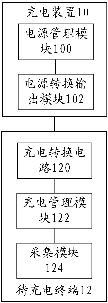
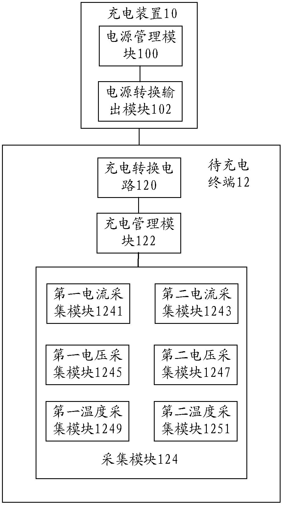
[0080] Figure 1a is a schematic structural diagram of a charging system according to an embodiment of the present application. Such as Figure 1a As shown, the charging system includes: a charging device 10 and a terminal 12 to be charged, wherein,

[0081] The charging device 10 includes: a power management module 100 and a power conversion output module 102 . in:

[0082] The power management module 100 is connected with the power conversion output module 102, and is used for communicating with the charging management module in the terminal to be charged, and generates a control command; the power conversion output module 102 is used for outputting an output corresponding to the control command according to the control command electric signal.

[0083] In an optional embodiment, the power management module 100 is used to communicate and identify the terminal to be charged before charging, and control the power conversion output module 102 according to the communication in...

Embodiment 2

[0291] An embodiment of the present invention provides a charging device, which is used to implement the method in Embodiment 1, such as Figure 18 As shown, the device includes:

[0292] The detection module 180 is used to detect the operating parameters of the terminal to be charged during the charging process, wherein the operating parameters are used to reflect the state of the terminal to be charged during the charging process;

[0293] The adjustment module 182, coupled with the detection module 180, is used to adjust the working state of the charging conversion circuit in the terminal to be charged according to the working parameters, wherein different working states correspond to different charging efficiencies.

[0294] It should be noted that each of the above-mentioned modules can be implemented by software or hardware. For the latter, it can be implemented in the following manner, but not limited thereto: the above-mentioned modules are located in the same processo...

Embodiment 3

[0297] Figure 19 is a schematic flowchart of another charging method according to an embodiment of the present invention. Such as Figure 19 As shown, the method includes:

[0298] Step S1902, determine the charging device type of the charging device connected to the terminal to be charged, wherein the charging device type includes: the first type that supports adjustment of the output electrical signal of the charging device; does not support the adjustment of the output electrical signal of the charging device The second type of , wherein the output electrical signal includes: output voltage and / or output current;

[0299] Step S1904, obtain the operating parameters of the terminal to be charged during the charging process, wherein the operating parameters are used to reflect the state of the terminal to be charged during the charging process; optionally, the operating parameters include: the state of the battery in the terminal to be charged, and the charging current in...


PUM


Abstract

The invention discloses a charging method and a device, a system, a charging circuit, a terminal and a charging system. The method comprises the steps: detecting work parameters of the terminal to becharged in a charging process, wherein the work parameters are used for reflecting a state of the terminal to be charged in a charging process; adjusting a work state of a charging conversion circuitin the terminal to be charged according to the work parameters, wherein different work states correspond to different charging efficiency. The method disclosed by the invention solves the technical problem that a charging scheme in a related technology has a poor charging efficiency and bad user experience.

Description

technical field [0001] The present invention relates to the field of charging, in particular to a charging method and device, a system, a charging circuit, a terminal, and a charging system. Background technique [0002] Terminals such as mobile phones have become life tools in various aspects such as communication interaction and digital entertainment, and large-capacity batteries have become a typical configuration of terminals. The large capacity of the battery and the pattern of frequent use make fast charging an important aspect of the end-user experience. As the charging rate of the battery increases, the charging current of the battery increases. How to make the battery obtain a larger charging current when charging the terminal, shorten the charging time, and improve the user experience of the terminal has become an important direction in the terminal research and development process. Especially when the USB organization releases USB PD 3.1, the VBUS of USB can supp...

Claims


Application Information

Patent Timeline
Patent Type & Authority Applications(China)
IPC IPC(8): H01M10/44H02J7/00
CPCH01M10/44H02J7/007H02J7/007192Y02E60/10H02J7/00712H02J7/007194H02J7/0048H02J7/007182
Inventor 龚勇
Owner ZTE CORP
Why Eureka
Try Eureka