
Microphone phase array calibration device

A phased array and calibration device technology, applied in electrical components and other directions, can solve the problems of poor positioning effect, difference, and reduction of sound source positioning accuracy, so as to avoid deviation, improve positioning effect, and improve the efficiency of measurement.

Active Publication Date: 2018-07-06
中国航空工业集团公司哈尔滨空气动力研究所
View PDF5 Cites 11 Cited by
  • Summary
  • Abstract
  • Description
  • Claims
  • Application Information

AI Technical Summary

Problems solved by technology

When using the microphone phase array to locate the noise source, due to various reasons such as the installation method of the array, the installation position, the difference in plugging and unplugging of the microphone, the deformation of the array frame, and the unevenness of the ground, it will bring various influences to the microphone phase array, resulting in the array There is a difference between the spatial coordinates of the microphone and the nominally given coordinates, and the positioning effect becomes poor, which reduces the accuracy of sound source positioning during noise testing

Method used


Image

  • Microphone phase array calibration device
  • Microphone phase array calibration device
  • Microphone phase array calibration device

Examples


Embodiment Construction

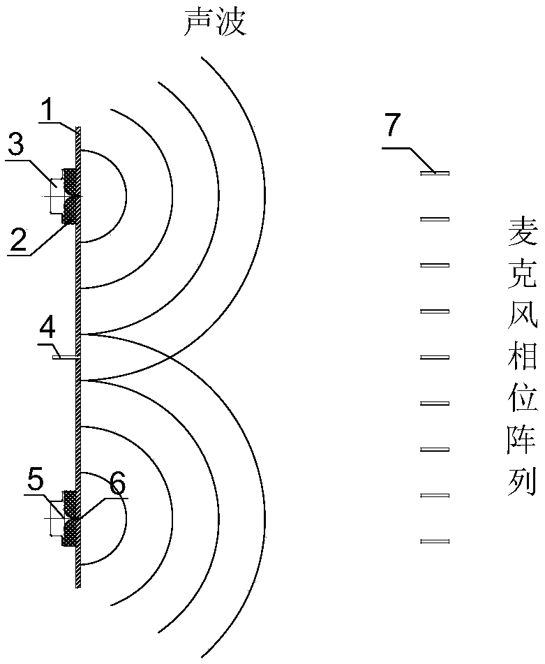
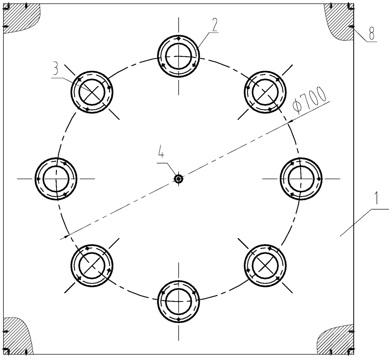
[0009] The present invention will be described in further detail below. see figure 1 , 2 , 3, microphone phase array calibration device, is characterized in that: it comprises calibration panel 1, loudspeaker mount 2, loudspeaker 3, reference microphone 4, sound transmission channel 5 and sound transmission hole 6. Calibration panel 1 is a larger size Rigid panel, with a hole in the center of the panel, used to install the reference microphone 4; several holes are opened on the circumference of the calibration panel with a certain diameter, used to install the speaker mount 2, the speaker mount is inserted into the mounting hole from the back of the calibration panel and ensured It is flush with the front of the calibration panel and connected by bolts; the other end of the speaker mounting base is used to install the speaker, and the speaker and the mounting base are connected by screws; there is a sound-transmitting channel 5 in the center of the speaker mounting base, and ...


PUM


Abstract

The invention belongs to the technical field of noise measurement, and relates to a microphone phase array calibration device for calibrating a microphone phase array for noise source positioning measurement. The device comprises a calibration panel (1), a speaker mounting base (2), a speaker (3), a reference microphone (4), a sound-permeable channel (5) and a sound-permeable aperture (6). The invention provides a microphone phase array calibration device, which improves the positioning effect and the positioning accuracy of the noise source.

Description

technical field [0001] The invention belongs to the technical field of noise measurement, and relates to a microphone phase array calibration device for calibrating the microphone phase array during noise source location measurement. Background technique [0002] Noise source location technology based on microphone phase array is currently the main means to realize noise source location and identification. When using the microphone phase array to locate the noise source, due to various reasons such as the installation method of the array, the installation position, the difference in plugging and unplugging of the microphone, the deformation of the array frame, and the unevenness of the ground, it will bring various influences to the microphone phase array, resulting in the array There is a difference between the spatial coordinates of the microphone and the nominally given coordinates, and the positioning effect becomes poor, which reduces the accuracy of sound source positi...

Claims


Application Information

Patent Timeline
Patent Type & Authority Applications(China)
IPC IPC(8): H04R29/00
CPCH04R29/005
Inventor 周国成周建成陈宝邵天双李元首
Owner 中国航空工业集团公司哈尔滨空气动力研究所
Learn More