Circuit layout applicable to narrow-border touch panel

A technology of touch panel and circuit layout, applied in the field of touch display equipment

Active Publication Date: 2018-07-10
INTERFACE TECH CHENGDU CO LTD +2
View PDF6 Cites 6 Cited by
  • Summary
  • Abstract
  • Description
  • Claims
  • Application Information

AI Technical Summary

Problems solved by technology

[0005] The main purpose of the present invention is to improve the pro...

Method used


Image

  • Circuit layout applicable to narrow-border touch panel
  • Circuit layout applicable to narrow-border touch panel
  • Circuit layout applicable to narrow-border touch panel

Examples


Embodiment Construction

[0048] In order to achieve the above-mentioned purpose and effect, the technical means and structure adopted by the present invention are hereby drawn in detail with respect to the preferred embodiments of the present invention. constituting the limitations of the invention.

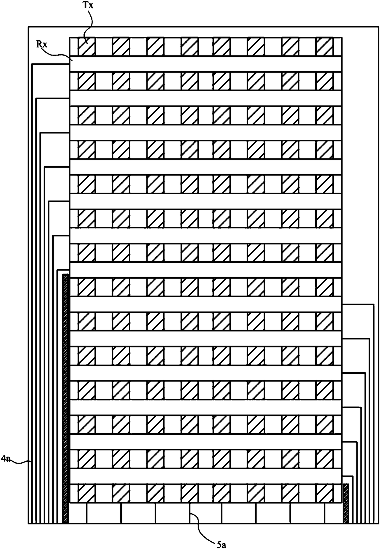
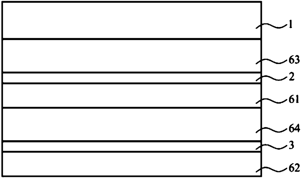
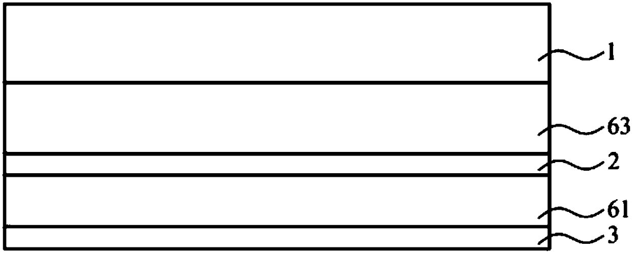
[0049] Please also see figure 2 , image 3 and Figure 4 As shown, it is a schematic diagram of the stacked structure of the touch structure of the preferred embodiment of the circuit layout suitable for narrow-frame touch panels of the present invention Figure 1 , touch structure layered structure diagram Figure II And a schematic diagram of the circuit layout of the conductive layer. The circuit layout applicable to the narrow frame touch panel of the present invention is applied to a touch panel and is formed on one of the conductive layers of the touch panel. The touch structure of a general touch panel generally includes: a cover plate 1 , a first conductive layer 2 and a second conductive l...


PUM


Abstract

The invention provides circuit layout applicable to a narrow-border touch panel. Transparent circuit routing is arranged in a cushion area between a border ink area and a visible area (touch functional area), a technology for arranging transparent circuit routing in the visible area is disclosed, so that metal circuit routing quantity in the border ink area is reduced. By means of the circuit layout, circuit routing design of the original touch panel is changed, the metal circuit routing quantity in the border ink area is reduced effectively, so that manufacture cost can be reduced, and the touch panel has a narrow-border effect.

Description

technical field [0001] The technology of the present invention relates to the field of touch display devices, and in particular refers to a touch panel that changes the layout of internal touch circuit wiring to achieve a narrow frame effect. Background technique [0002] The touch panel is widely used in the external port input interface of the instrument due to its characteristics of human-computer interaction and diversified design. In recent years, with the wide application of consumer electronics products, more and more products are applied with the combination of touch function and display, such as mobile phone, GPS navigator system, tablet Computer (tablet PC), and notebook computer (laptop PC), etc. [0003] With the advancement of science and technology, people have higher and higher requirements for the quality of electronic products. Under the fierce competition, electronic manufacturers are aiming at beauty, lightness, thinness, and narrowness. At the same time,...

Claims


Application Information

Patent Timeline
IPC IPC(8): G06F3/041
CPCG06F3/0412G06F3/0416G06F2203/04103
Inventor 李炫运
Owner INTERFACE TECH CHENGDU CO LTD
Why Eureka
Try Eureka