A revit-based transfer station standard template drawing method and transfer station construction method
A standard template and transfer station technology, applied in geometric CAD, special data processing applications, etc., can solve problems such as low work efficiency, high learning costs, time-consuming modeling accuracy, etc., to simplify the drawing process, shorten time, Fast and accurate drawing effects
- Summary
- Abstract
- Description
- Claims
- Application Information
AI Technical Summary
Problems solved by technology
Method used
Image
Examples
Embodiment 1
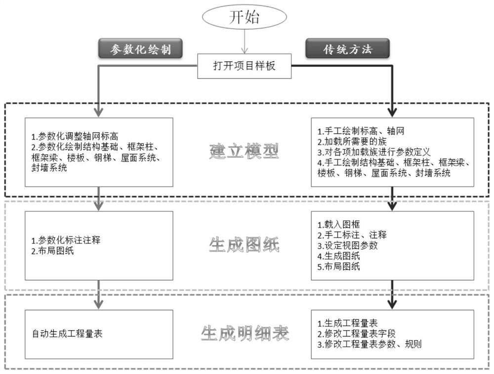
[0097] There are many defects in the drawing of the BIM model of the steel structure transfer station using the traditional drawing method. Therefore, the parametric standard template drawing method of the steel structure transfer station is used instead of the traditional drawing method.
[0098] Such as figure 1 As shown, the drawing of the BIM model of the steel structure transfer station in this scheme no longer uses the traditional blank structural template, but uses the components of the steel structure transfer station that have been preset, binds the data relationship between the components, and presets standardized construction The steel structure transfer station template with drawings and engineering quantities is ready for parametric modeling. The completed steel structure transfer station drawing files, combined with the redesign of the steel structure transfer station BIM model drawing process, can quickly establish a steel structure transfer station BIM model. ...
Embodiment 2
[0137] The parametric formwork of the steel structure transfer station in Example 1 is adopted, and the specific implementation method is as follows:
[0138] Based on the above design ideas, various components, construction drawings, and engineering quantities required for drawing the BIM model of the steel structure transfer station are preset, and a parametric drawing template for the steel structure transfer station is established.
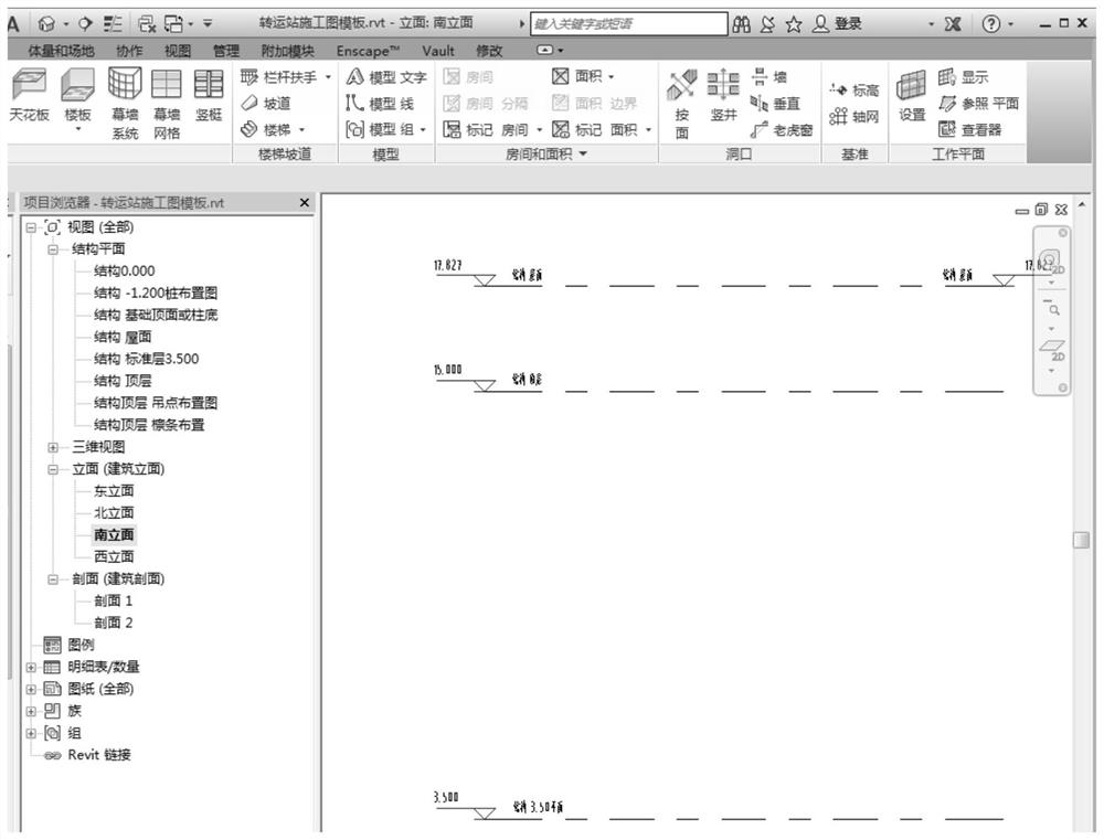
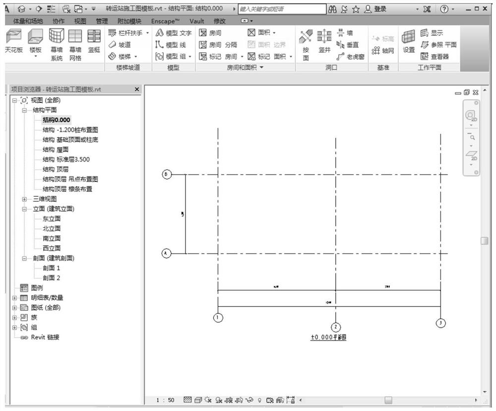
[0139] (1) Preset axis network and elevation: preset plus or minus 0 elevation, 4 elevations of column bottom elevation, standard floor elevation, and roof elevation. Such as figure 2 As shown, the labels of the two grids A and B in the preset horizontal direction; for example image 3As shown, the three longitudinal grids are numbered 1, 2, and 3. Among them, the 1 axis and the A axis are arranged on the project base point in the positive and negative 0 elevations, and the grid distance is marked.
[0140] (2) if Figure 4 As shown, the ...
Embodiment 3
[0152] Based on the template of embodiment 1, carry out the method for the construction of transfer station, concrete method is as follows:
[0153] 1. Select a template
[0154] Select to open the "3D Design Standard Template for Steel Structure Transfer Station.rvt" file.
[0155] Second, draw the axis and elevation
[0156] Adjust the axis position on the positive and negative zero planes, and draw the elevation.
[0157] 3. Drawing basics
[0158] The independent foundation under the column has been placed in the template, and the calculation is carried out according to the size of the model and the size required by this plan. If the original model is set according to 500*400, according to the calculation result and the design type, the independent foundation is modified to the required foundation type, and the drawing Structural basis.
[0159] 4. Draw the frame columns
[0160] Frame columns have been placed at each network point in the formwork, and then according ...
PUM
 Abstract
Description
Claims
Application Information
 - R&D
- Intellectual Property
- Life Sciences
- Materials
- Tech Scout
- Unparalleled Data Quality
- Higher Quality Content
- 60% Fewer Hallucinations
Browse by: Latest US Patents, China's latest patents, Technical Efficacy Thesaurus, Application Domain, Technology Topic, Popular Technical Reports.
© 2025 PatSnap. All rights reserved.Legal|Privacy policy|Modern Slavery Act Transparency Statement|Sitemap|About US| Contact US: help@patsnap.com


