
Assembling device of electrical connector

A technology for assembling equipment and electrical connection sheets, which is applied in the assembly/disassembly of contacts, manufacturing of contacts, etc., which can solve the problem that the functions are not perfect, cannot meet the diversified requirements of the assembly of electrical connection sheets, and does not specifically explain bolts and electrical connections. Sheet and metal tube feeding process and other issues

Pending Publication Date: 2018-07-10
ANHUI NORMAL UNIV
View PDF1 Cites 0 Cited by
  • Summary
  • Abstract
  • Description
  • Claims
  • Application Information

AI Technical Summary

Problems solved by technology

[0003] The patent with the patent number CN201720715408.6 discloses the transfer mechanism of the electrical connector. The patent only elaborates on the transfer steps of specific bolts, electrical connectors and metal pipes, and does not specifically elaborate on the bolts, electrical connectors and metal tubes. Therefore, it is impossible to know whether the feeding process can be automated, and the assembly mechanism in this patent can only be assembled for one type of electrical connector, and cannot meet the assembly of other types of electrical connectors, so Its function is not perfect, and it cannot meet the diversified requirements of electrical connector assembly in the actual use process

Method used


Image

  • Assembling device of electrical connector
  • Assembling device of electrical connector
  • Assembling device of electrical connector

Examples


Embodiment Construction

[0028] Below in conjunction with accompanying drawing and embodiment of description, specific embodiment of the present invention is described in further detail:

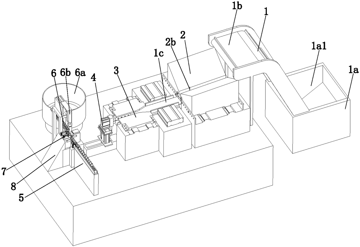
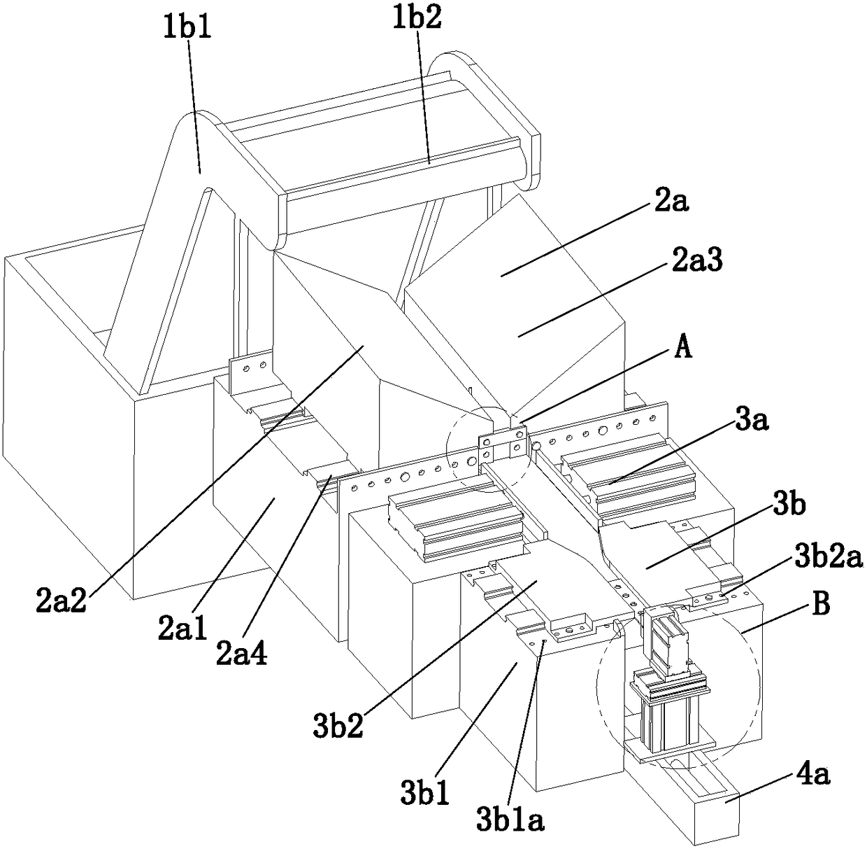
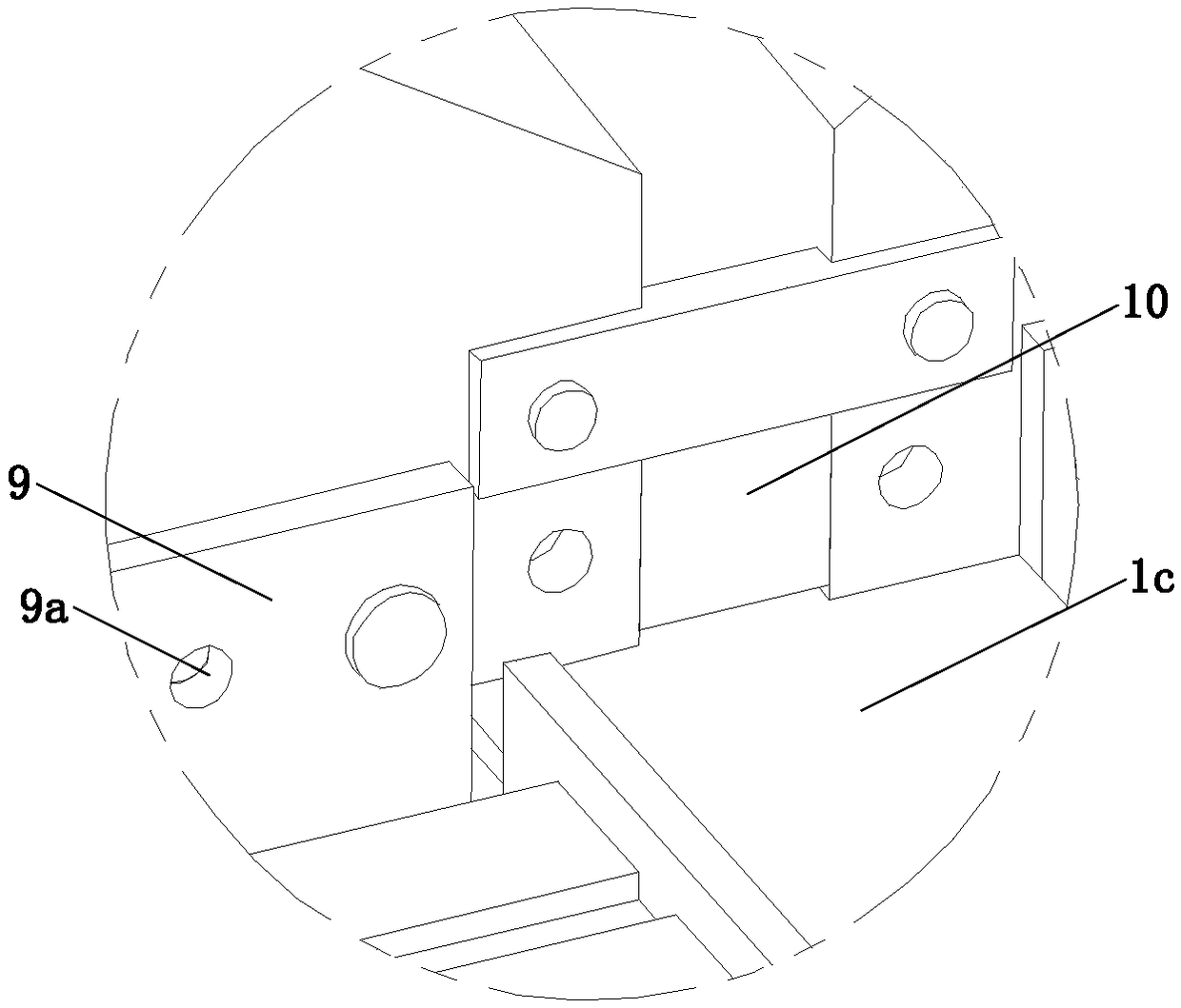
[0029] refer to Figure 1 to Figure 11An assembly device for electrical connectors, comprising a feeding mechanism 1, an orientation mechanism 2, a positioning mechanism 3, a first transfer mechanism 4, a second transfer mechanism 5, a bolt assembly mechanism 6 and a conveying mechanism 7, the orientation mechanism 2 and The positioning mechanism 3 is installed on both sides of the feeding mechanism 1, the first transfer mechanism 4 is located between the conveying mechanism 7 and the positioning mechanism 3, the bolt assembly mechanism 6 and the second transfer mechanism 5 are symmetrically arranged on both sides of the conveying mechanism 7, The conveying mechanism 7 includes a mounting base 7a, a fixed block 7b, a first conveying assembly 7c, a second conveying assembly 7d, and a pressing assembly 7e. On the sid...


PUM


Abstract

The present invention relates to the field of mechanical equipment, especially to an assembling device of an electrical connector. The assembling device comprises a feed mechanism, an orienteering mechanism, a positioning mechanism, a first transfer mechanism, a second transfer mechanism, a bolt assembling mechanism and a transmission mechanism. The orienteering mechanism is located below the tailend of the feed mechanism, the positioning mechanism is located at the tail end of the orienteering mechanism, the first transfer mechanism is located between the transmission mechanism and the positioning mechanism, the bolt assembling mechanism and the second transfer mechanism are symmetrically arranged at two sides of the transmission mechanism, the transmission mechanism comprises an installation seat, a fixed block, a first transmission module, a second transmission module and a compressing module, the fixed block is fixedly connected with the installation seat through a bolt, and the middle portion of the fixed block is provided with a penetrating hole. The assembling device of the electrical connector can achieve automatic assembling of the electrical connector, the bolt and a metal tube, can perform regulation according to specification and dimension of the electrical connector and can be suitable for assembling of different electrical connectors.

Description

technical field [0001] The invention relates to the field of mechanical equipment, in particular to an assembly equipment for electrical connecting sheets. Background technique [0002] With the wide application of electric energy, more and more electrical connectors are used. With the diversification and complexity of circuit connections, an electrical connector needs to have multiple connectors. Therefore, electrical connectors generally need to use The electrical connecting piece connects multiple connectors. There is a through hole corresponding to each connecting head on the electrical connecting piece, and a bolt is placed in each through hole. Before the electrical connecting piece is used, it is necessary to install the bolt in order to prevent the bolt from falling off. A metal tube is installed at the lower end of the metal tube and the upper end of the metal tube is squeezed and deformed so that the metal tube is engaged with the bolt. [0003] The patent with th...

Claims


Application Information

Patent Timeline
IPC IPC(8): H01R43/16H01R43/20
CPCH01R43/16H01R43/20
Inventor 吴长义李琦琦许晨晨宋凤楼
Owner ANHUI NORMAL UNIV
Learn More