Industrial waste gas purifying device and operating method

A technology for industrial waste gas and purification devices, applied in chemical instruments and methods, separation methods, combined devices, etc., can solve the problems of high energy consumption, guaranteed treatment, difficult to form dispersion, etc., and achieve the effect of low energy consumption

Inactive Publication Date: 2018-07-13
王玉玲
View PDF8 Cites 10 Cited by
  • Summary
  • Abstract
  • Description
  • Claims
  • Application Information

AI Technical Summary

Problems solved by technology

[0008] One: For the exhaust gas discharged from the workshop, it is usually sent directly to the purification device body during treatment, but the exhaust gas is usually partially excluded inside the purification device body, so it is difficult to form a relatively uniform dispersion, and the exhaust gas gradually passes through the device. It is difficult to accumulate to the spray mechanism during the rising process, which will affect the effect of purification treatment;
[0009] Second: For the existing industrial exhaust gas purification device, the energy consumption is high in the process of spraying the purification liquid, and the sprayed purification liquid is difficult to disperse in the device;
[0010] Third: The existing industrial exhaust gas purification devices lack a circulation path for detecting and pumping the purified gas during use, which is not conducive to the guaranteed treatment of air quality

Method used


Image

  • Industrial waste gas purifying device and operating method
  • Industrial waste gas purifying device and operating method
  • Industrial waste gas purifying device and operating method

Examples


Embodiment Construction

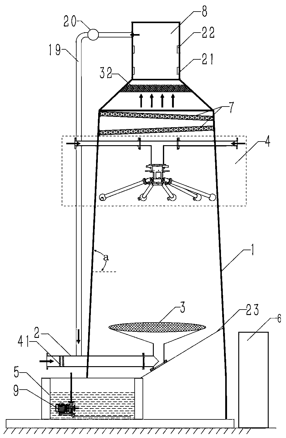
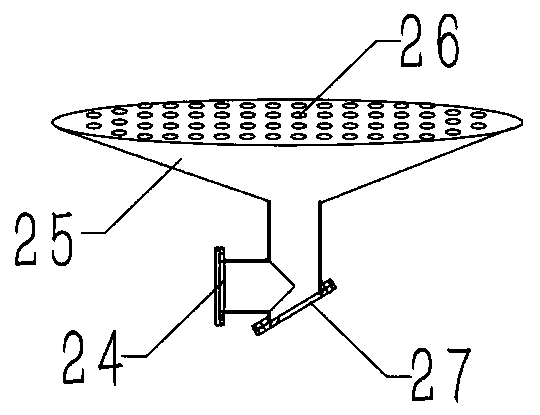
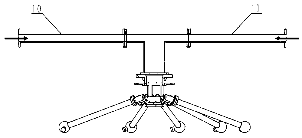
[0066] The following will be combined with Figure 1-Figure 7The present invention is described in detail, and the technical solutions in the embodiments of the present invention are clearly and completely described. Apparently, the described embodiments are only some of the embodiments of the present invention, not all of them. Based on the embodiments of the present invention, all other embodiments obtained by persons of ordinary skill in the art without making creative efforts belong to the protection scope of the present invention.

[0067] The present invention provides a kind of industrial waste gas purification device here through improvement, as Figure 1-Figure 7 As shown, it can be implemented in the following manner; the exhaust gas purification device includes a purification shell 1, an exhaust gas delivery intake pipe 2, an exhaust gas distribution mechanism 3, an exhaust gas purification rotary spray mechanism 4, a purification liquid storage and collection box 5...


PUM


Abstract

The invention discloses an industrial waste gas purifying device and an operating method. The industrial waste gas purifying device comprises a purifying shell, a waste gas conveying gas inlet pipe, awaste gas diffusing mechanism, a waste gas purifying rotary sprinkling mechanism, a purified liquid storing and collecting box, a control box and two sprinkling purifying filter layers, wherein one end of the waste gas conveying gas inlet pipe stretches out of the purifying shell, and the other end of the waste gas conveying gas inlet pipe is connected with the lower end of the waste gas diffusing mechanism; the waste gas purifying rotary sprinkling mechanism comprises a first liquid inlet pipe, a second liquid inlet pipe, a fixed connecting component, a rotary connecting end socket, a rotaryconnecting component, connecting connectors, rotary sprinkling rods, rotary sprinkling heads and a plug; a sprinkling circulating pump is arranged inside the purified liquid storing and collecting box. After improvement, industrial waste gas is conveyed therein through the waste gas conveying gas inlet pipe and is slowly and uniformly diffused in the purifying shell through multiple gas diffusingholes corresponding to the waste gas diffusing mechanism; in addition, liquid can be uniformly and rapidly sprinkled in a sprinkling way, and the energy consumption is relatively low in the whole process.

Description

technical field [0001] The invention relates to the field of industrial waste gas purification, in particular to an industrial waste gas purification device and an operation method. Background technique [0002] With the rapid development of my country's national economy, especially the development of the chemical industry and manufacturing industry, the discharge of industrial waste gas is increasing. The total amount of pollutant gas. Exhaust gas contains a large amount of harmful bacteria, viruses and organic gases, and these substances emit foul odor, which is one of the important factors causing air pollution. Most of these industrial waste gases are irritating to the eyes, mucous membranes of the respiratory tract and skin. Working in such a harsh environment for a long time, the body is vulnerable to injury and threatens people's health. If these industrial waste gases are directly discharged into the air without treatment, it will be harmful Serious pollution to the...

Claims


Application Information

Patent Timeline
Patent Type & Authority Applications(China)
IPC IPC(8): B01D53/00B01D53/30B01D53/75B01D53/78B01D53/96B01D46/00B01D46/12B01D46/30B01D47/08B01D50/00
CPCB01D46/0034B01D46/0036B01D46/12B01D46/30B01D47/08B01D53/005B01D53/30B01D53/75B01D53/78B01D53/96B01D2257/91B01D2258/02B01D46/64B01D50/60
Inventor 王玉玲
Owner 王玉玲
Why Eureka
Try Eureka