
Manned multi-rotor flying vehicle

A multi-rotor and vehicle technology, applied in the field of aircraft, can solve the problems of increasing the driver's safety risk, unsuitable flight environment, low sailing speed, etc., and achieve the effects of ensuring safety and comfort, simple structure, and reliable control.

Pending Publication Date: 2018-07-13
长沙市云智航科技有限公司
View PDF0 Cites 6 Cited by
  • Summary
  • Abstract
  • Description
  • Claims
  • Application Information

AI Technical Summary

Problems solved by technology

The aileron of the wing cooperates with the steering of the horizontal tail, through the lifting of the aileron, the fuselage is tilted, and the corner is turned by the action of centrifugal force. This method requires the aircraft itself to have a tilting effect, and it will increase the number of drivers when it is applied to a personal aircraft. safety risk, not suitable for personal aircraft use
[0004] The other is a rotorcraft, in which the rotor is mainly used to form lift, and the flight speed can only be realized by adjusting the attitude to form a lateral resultant force, resulting in a large energy consumption and a low navigation speed
In addition, most of the rotorcraft realize the attitude change of the aircraft by changing the output power of the aircraft engine or changing the pitch of the blades; in order to make the aircraft fly smoothly, it is necessary to accurately calculate the rotational speed of the engine and change the pitch of the blades when adjusting each flight attitude. Pitch, the process is cumbersome, not suitable for complex and changeable flight environments, and there will still be tilts during flight, which also increases the safety risk of the driver

Method used


Image

  • Manned multi-rotor flying vehicle
  • Manned multi-rotor flying vehicle
  • Manned multi-rotor flying vehicle

Examples


Embodiment Construction

[0055] The present invention will be further described below in conjunction with the accompanying drawings and specific embodiments.

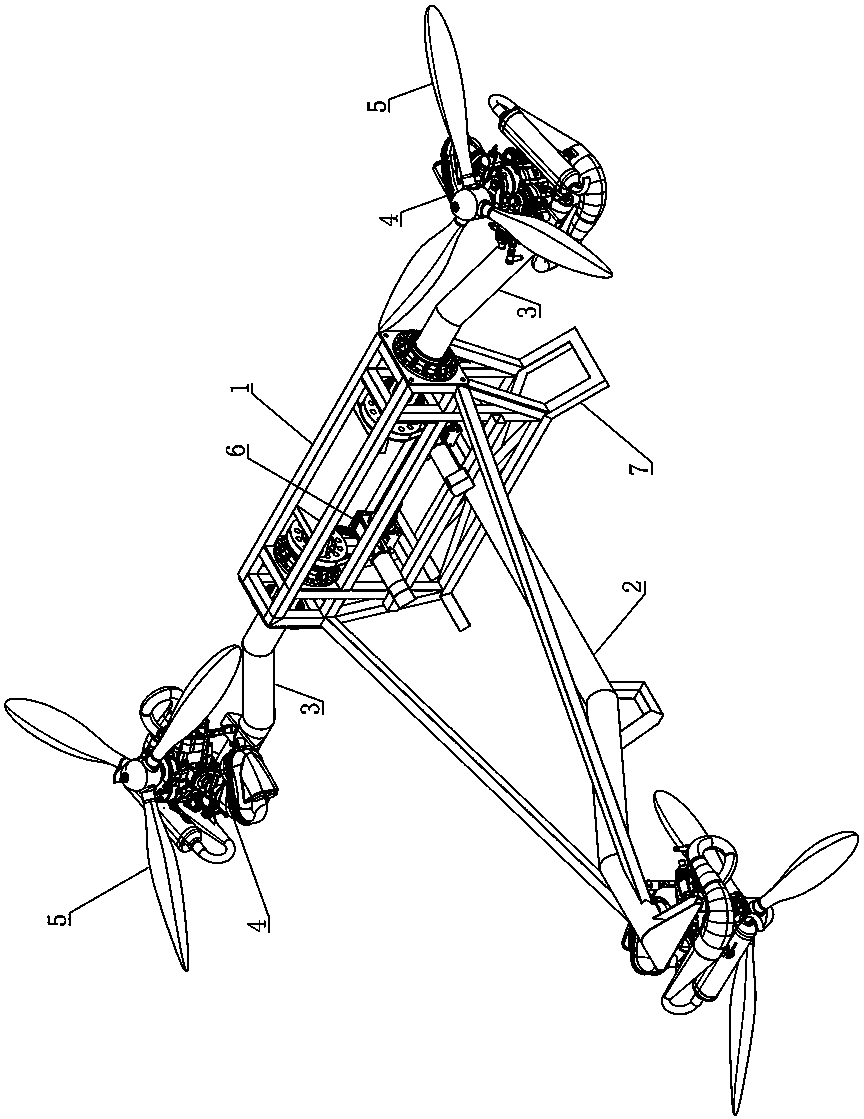
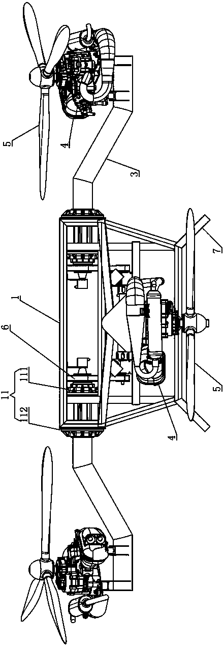
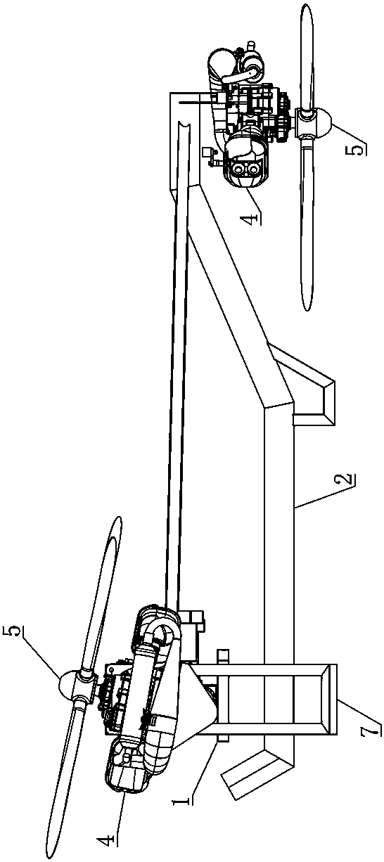
[0056] Such as Figure 1 to Figure 14 As shown, the manned multi-rotor flying vehicle of this embodiment is specifically a flying motorcycle or a flying car. The structure includes a keel-type frame 1, and a fixed arm 2 extending outward is provided directly in front of or directly behind the frame 1. Both sides of the frame 1 are symmetrically provided with more than one tilting machine arm 3 extending outward, and the ends of the fixed machine arm 2 and each tilting machine arm 3 are fixedly installed with a power assembly 4, and a rotor 5 is installed on the power assembly 4. The power assembly 4 is used to drive the rotor 5 to rotate to generate lift; the tilting assembly 6 is arranged between the frame 1 and each tilting arm 3, and is used to drive the tilting arm 3 to rotate to adjust the orientation of the rotor 5 on the tilting arm 3 (...


PUM


Abstract

The invention discloses a manned multi-rotor flying vehicle. The manned multi-rotor flying vehicle comprises a frame, wherein a fixed machine arm is arranged in front of or directly behind the frame;one or more tilting machine arms are symmetrically and rotationally arranged on two sides of the frame; the tail ends of the fixed machine arm and each tilting machine arm are fixedly provided with apower assembly respectively; a rotor is mounted on the power assembly; the tilting assemblies are arranged between the frame and each tilting machine arm, and are used for driving the tilting machinearm to rotate so as to adjust the inclination of the rotor on the tilting machine arm along the front-back direction of the frame. The manned multi-rotor flying vehicle provided by the invention has the advantages of simple structure, safety and comfort, simple and convenient control, long cruise range and the like.

Description

technical field [0001] The invention mainly relates to the field of aircraft technology, in particular to a manned multi-rotor flying vehicle. Background technique [0002] At present, small aircraft are mostly used to carry various measuring instruments (such as cameras, etc.) for high-altitude detection or high-altitude object throwing, and can be used in various fields such as agriculture, detection, meteorology, disaster forecasting, and rescue. However, small aircraft that can carry people are rare, and there is a lot of room for research. [0003] Existing aircraft is divided into two kinds of fixed wing aircraft and rotary wing aircraft. Fixed-wing aircraft mainly achieve flight by obtaining a large initial velocity and forming lift on the wing surface, but they cannot hover, have poor stability at low speeds, are prone to crashes due to stalls, and require a large sliding distance. In addition, fixed-wing aircraft generally use two methods for steering, one is pure...

Claims


Application Information

Patent Timeline
IPC IPC(8): B64C27/08B64C27/12B64C27/52B64D33/08
CPCB64C27/08B64C27/12B64C27/52B64D33/08B64C2027/125
Inventor 袁启
Owner 长沙市云智航科技有限公司
Learn More