Special conveying device for electromechanical manufacturing

A conveying device and technology of technical secondary school, applied in the direction of transportation and packaging, containers to prevent mechanical damage, packaging, etc., can solve the problems of easy damage, economic loss, and easy damage of electromechanical equipment, so as to achieve the goal of not being easily damaged and reducing the economic cost. Loss, low production cost effect

Inactive Publication Date: 2018-07-13
NANTONG PRATT MACHINERY
View PDF5 Cites 6 Cited by
  • Summary
  • Abstract
  • Description
  • Claims
  • Application Information

AI Technical Summary

Problems solved by technology

Electromechanical manufacturing provides technical equipment for the entire national economy; currently, when electromechanical equipment is transported in electromechanical manufacturing, the electromechanical equipment will be vibrated during the transportation process, making the parts on the electromechanical equipment easily damaged; and the position of the electromechanical equipment is not fixed. , prone to collisions during transportation, resulting in more damage to electromechanical equipment and economic losses. Therefore, it is urgent to develop a shock-absorbing function, which is protected during transportation of electromechanical equipment, so that electromechanical equipment is not easily damaged and reduces the cost. Mechanical and Electrical Equipment Transportation Devices for Economic Loss

Method used


Image

  • Special conveying device for electromechanical manufacturing

Examples


Embodiment Construction

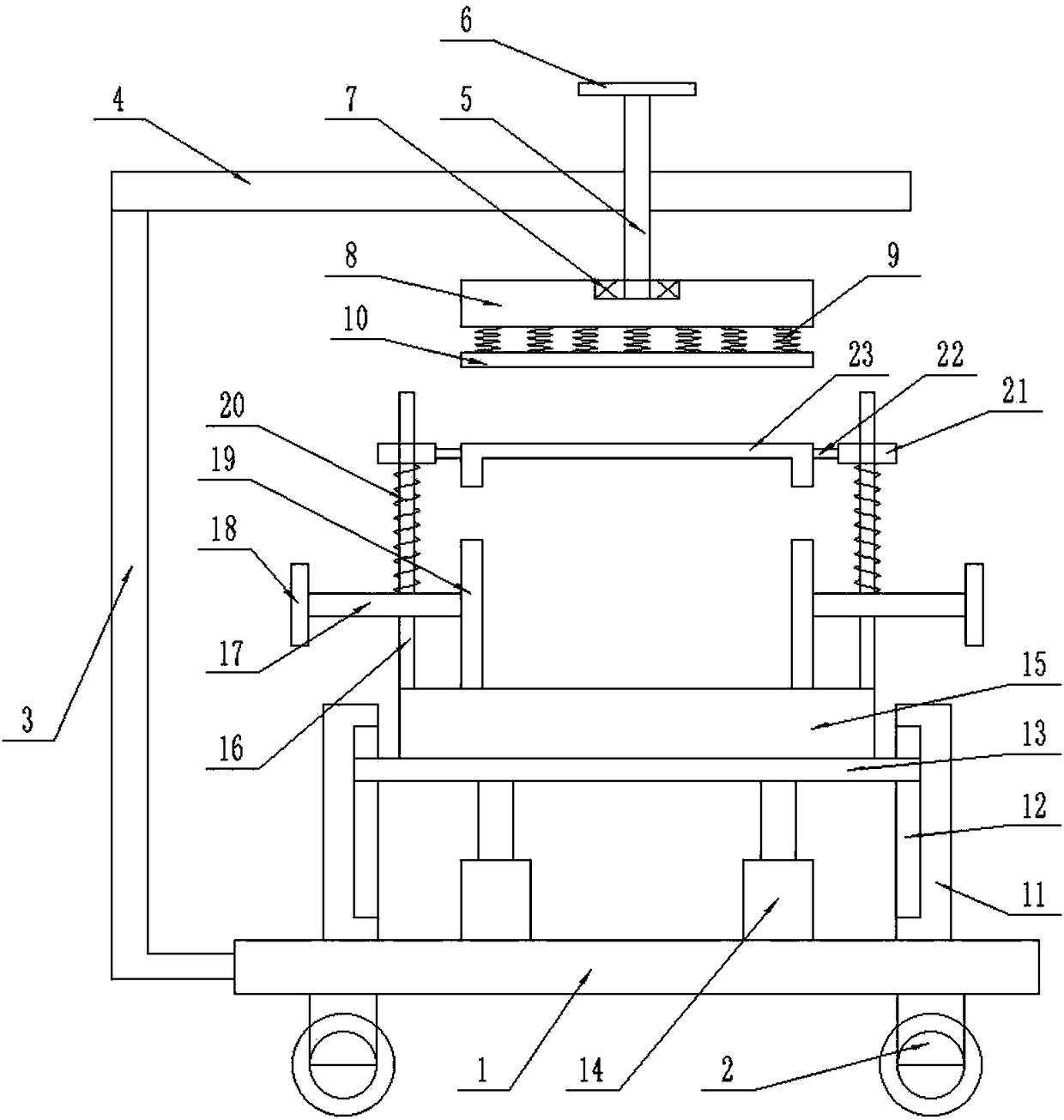
[0012] Such as figure 1 As shown, this specific embodiment adopts the following technical solutions: a special conveying device in electromechanical manufacturing, including a base 1, a universal wheel 2, an L-shaped bar 3, a cross bar 4, a first screw rod 5, a first handle 6, a bearing 7. Pressure seat 8, spring 9, pressure plate 10, vertical plate 11, groove 12, slide plate 13, hydraulic cylinder 14, fixed seat 15, column 16, second screw rod 17, second handle 18, clamp block 19, rebound Spring 20, slide block 21, connecting rod 22 and recessed word seat 23; The lower surface of described base 1 is provided with several universal wheels 2; The left side surface of described base 1 is fixedly connected with an L-shaped bar 3; A crossbar 4 is fixedly connected to the top of the L-shaped rod 3; a first screw 5 is threadedly connected to the crossbar 4; a first handle 6 is fixedly connected to the top of the first screw 5; The end of the first screw 5 is movably connected to th...


PUM


Abstract

The invention discloses a special conveying device for electromechanical manufacturing. The special conveying device is reasonable and simple in structure, the production cost is low, the installationis convenient, and the functions are complete. The electromechanical equipment is fixed above a fixing base, second handles are rotated, clamp blocks clamp the electromechanical equipment, universalwheels are transported, and the height of the fixed seat is adjusted by hydraulic cylinders; a first handle is rotated, a pressing seat is descended, the lower end of the pressing seat is connected with a pressing plate through springs, the pressing plate presses a concave character base tightly, and the concave character base presses the electromechanical equipment tightly; and the springs and rebound springs are arranged, so that the electromechanical equipment is enabled not easy to vibrate in a transportation process, so that the electromechanical equipment is protected, the damping function is achieved, protection is carried out when the electromechanical equipment is transported, the electromechanical equipment is enabled not easy to be damaged, and the economic loss effect is reduced.

Description

Technical field: [0001] The invention relates to the technical field of electromechanical manufacturing, in particular to a special conveying device in electromechanical manufacturing. Background technique: [0002] Mechanical and electrical manufacturing refers to the industrial sector engaged in the production of various power machinery, lifting and transportation machinery, chemical machinery, textile machinery, machine tools, tools, instruments, meters and other mechanical equipment. Electromechanical manufacturing provides technical equipment for the entire national economy; currently, when electromechanical equipment is transported in electromechanical manufacturing, the electromechanical equipment will be vibrated during the transportation process, making the parts on the electromechanical equipment easily damaged; and the position of the electromechanical equipment is not fixed. , prone to collisions during transportation, resulting in more damage to electromechanica...

Claims


Application Information

Patent Timeline
Patent Type & Authority Applications(China)
IPC IPC(8): B65D25/24B65D81/07B65D25/10
CPCB65D25/24B65D25/101B65D81/07
Inventor 花世军刘忠军
Owner NANTONG PRATT MACHINERY
Why Eureka
Try Eureka