Heat-radiating power cabinet mounted in clamped mode

A power cabinet and electric power technology, applied in the direction of electrical components, substation/power distribution device shell, substation/switch layout details, etc., can solve the problems of single structure of power cabinet, influence on construction efficiency, failure of power components, etc., and achieve good heat dissipation effect , Improve construction efficiency and facilitate maintenance

Inactive Publication Date: 2018-07-13
HUNAN XIANGXUN ENTERPRISE MANAGEMENT CO LTD
View PDF5 Cites 6 Cited by
  • Summary
  • Abstract
  • Description
  • Claims
  • Application Information

AI Technical Summary

Problems solved by technology

[0003] With the rapid development of power technology, the power cabinet is a commonly used power infrastructure, which is equipped with a large number of power components. When the power cabinet is working, a large amount of heat will be generated inside. Therefore, the side wall of the power cabinet must be Set up he

Method used


Image

  • Heat-radiating power cabinet mounted in clamped mode
  • Heat-radiating power cabinet mounted in clamped mode
  • Heat-radiating power cabinet mounted in clamped mode

Examples


Example Embodiment

[0019] The following will clearly and completely describe the technical solutions in the embodiments of the present invention with reference to the accompanying drawings in the embodiments of the present invention. Obviously, the described embodiments are only some, not all, embodiments of the present invention. Based on the embodiments of the present invention, all other embodiments obtained by persons of ordinary skill in the art without making creative efforts belong to the protection scope of the present invention.

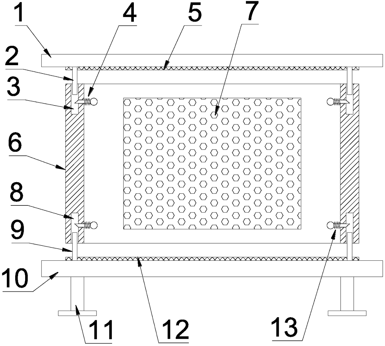
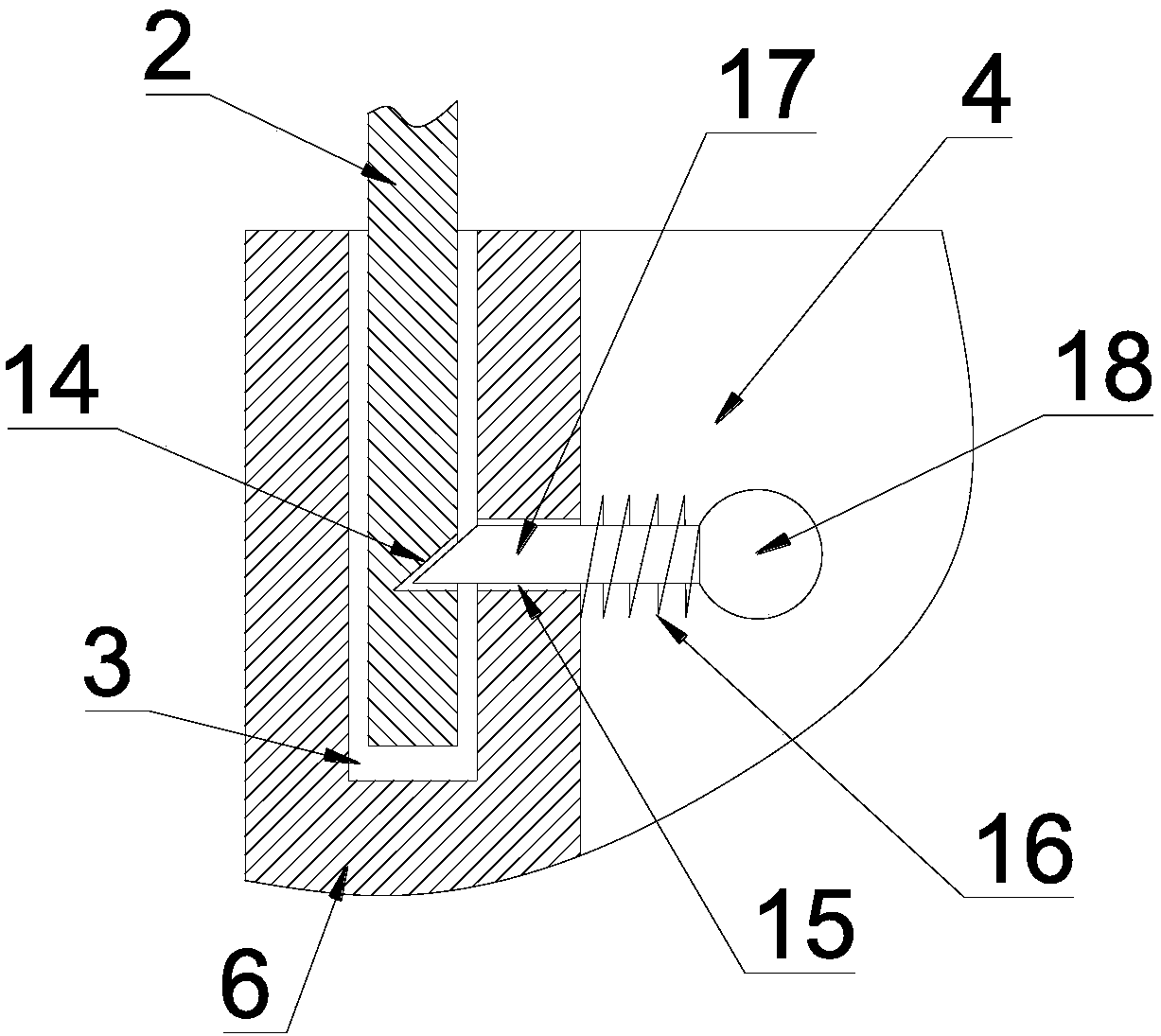
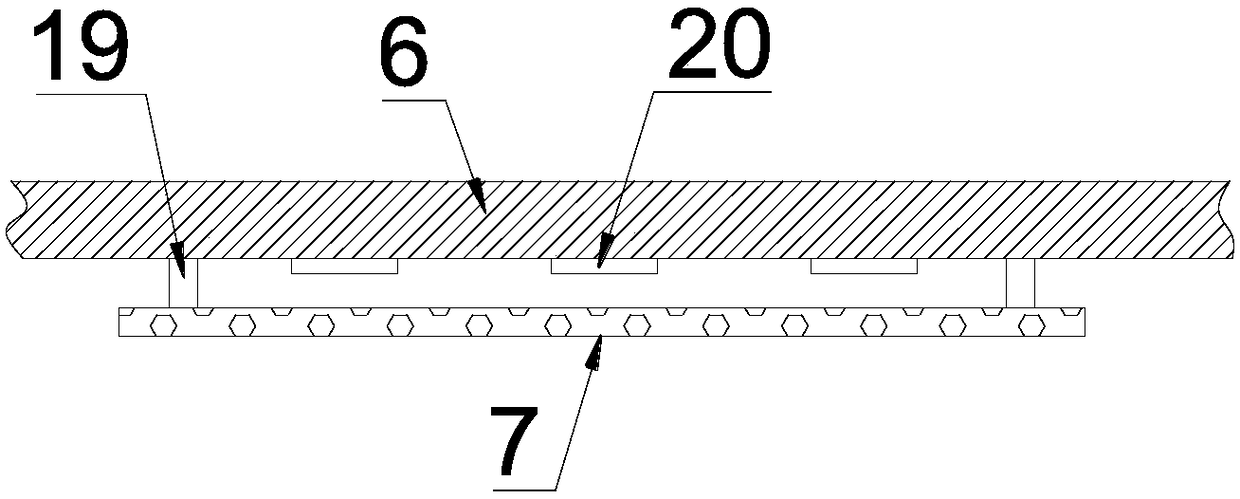
[0020] see Figure 1~3 , in the embodiment of the present invention, a snap-fit ​​heat dissipation power cabinet includes a top plate 1, a power cabinet body 6, a base 10 and legs 11, an electrical component mounting plate 7 is provided on the inner side of the power cabinet body 6, and the The electrical component mounting plate 7 is a rectangular porous ceramic plate, and the electrical component mounting plate 7 is parallel to the rear side inner wall of th...


PUM


Abstract

The invention discloses a heat-radiating power cabinet mounted in a clamped mode. The heat-radiating power cabinet comprises a top plate, a power cabinet body, a base and support legs. An electric component mounting plate is arranged on the inner side of the power cabinet body. The top plate and the base are respectively arranged at the top and the bottom of the power cabinet body. The support legs are arranged at the bottom of the base. A plurality of upper insertion rods are mounted on the outer ring of the lower side of the top plate. Upper insertion grooves matched with the upper insertionrods are correspondingly formed in the top of the power cabinet body. A plurality of lower insertion rods are mounted on the outer ring of the upper side of the base. Lower insertion grooves matchedwith the lower insertion rods are correspondingly formed in the bottom of the power cabinet body. Fixing holes communicated with the upper insertion grooves and the lower insertion grooves are formedin the inner wall of the power cabinet body. Upper clamping components are mounted on the fixing holes corresponding to the upper insertion grooves. Lower clamping components are mounted on the fixingholes corresponding to the lower insertion grooves. The heat-radiating power cabinet has the advantages of novel structure, reasonable design, convenience in mounting and demounting, stability, reliability, improved construction efficiency, good heat radiation effect, convenience in later-period maintenance, and popularization and application benefiting.

Description

technical field [0001] The invention relates to the field of electric equipment, in particular to a heat-dissipating electric power cabinet with clamping installation. Background technique [0002] Power equipment mainly includes power generation equipment and power supply equipment. Power generation equipment is mainly power plant boilers, steam turbines, gas turbines, water turbines, generators, transformers, etc. Power supply equipment is mainly transmission lines of various voltage levels, transformers, contactors, etc. Devices, power cabinets, distribution cabinets, etc. [0003] With the rapid development of power technology, the power cabinet is a commonly used power infrastructure, which is equipped with a large number of power components. When the power cabinet is working, a large amount of heat will be generated inside. Therefore, the side wall of the power cabinet must be A heat dissipation window is set up, but only through the heat dissipation window to dissipa...

Claims


Application Information

Patent Timeline
IPC IPC(8): H02B1/30H02B1/34H02B1/56
CPCH02B1/30H02B1/34H02B1/565
Inventor 何辉
Owner HUNAN XIANGXUN ENTERPRISE MANAGEMENT CO LTD
Why Eureka
Try Eureka