Hot plate mold for automobile lamp housing manufacturing equipment

A technology for manufacturing equipment and shells, applied in the field of hot plate molds, can solve the problems of affecting the welding effect of the edge of the lamp shell, uneven heating of the welding ribs, inconvenient mold replacement, etc., to reduce weight and cost, easy operation, and energy consumption. Effect

Pending Publication Date: 2018-07-17
JIANGSU YEDI AUTOMOTIVE LIGHTING SYST
View PDF7 Cites 1 Cited by
  • Summary
  • Abstract
  • Description
  • Claims
  • Application Information

AI Technical Summary

Problems solved by technology

In the prior art, the above-mentioned production is generally completed by adding welding ribs into the hot plate mold of the welding machine and hot pressing. Usually, the hot plate mold for making this type of car lamp housing is composed of an upper mold, a middle and upper mold, a middle and lower mold and The lower mold consists of four parts, among which the upper middle and the lower are hot molds. The hot molds in the prior art need to be heated as a whole, and the hot mold molds near the welding ribs need to be heated by adding heating tubes. The hot plate of this mode has the following Disadvantages: First, the hot plate mold is relatively heavy, which is inconvenient to replace the mold; second, the hot plate mold is solid, which will cause the parts of the lamp housing that do not need to be welded to become foggy and white due to the inability to dissipate heat in time; There are many heating tubes installed in the hot plate mold, each of which needs to be connected with a wire to be energized. The cost is high and the operation is complicated. Moreover, because the hot plate mold is irregular in shape, the heating of each part of the welding rib is uneven, which affects the edge of the lamp housing. Welding effect; thirdly, the temperature rises slowly during use, and the energy consumption is relatively large, and the cooling is relatively slow when changing the mold, which affects work efficiency

Method used


Image

  • Hot plate mold for automobile lamp housing manufacturing equipment
  • Hot plate mold for automobile lamp housing manufacturing equipment
  • Hot plate mold for automobile lamp housing manufacturing equipment

Examples


Embodiment Construction

[0013] The present invention will be further described below in conjunction with the accompanying drawings and specific embodiments.

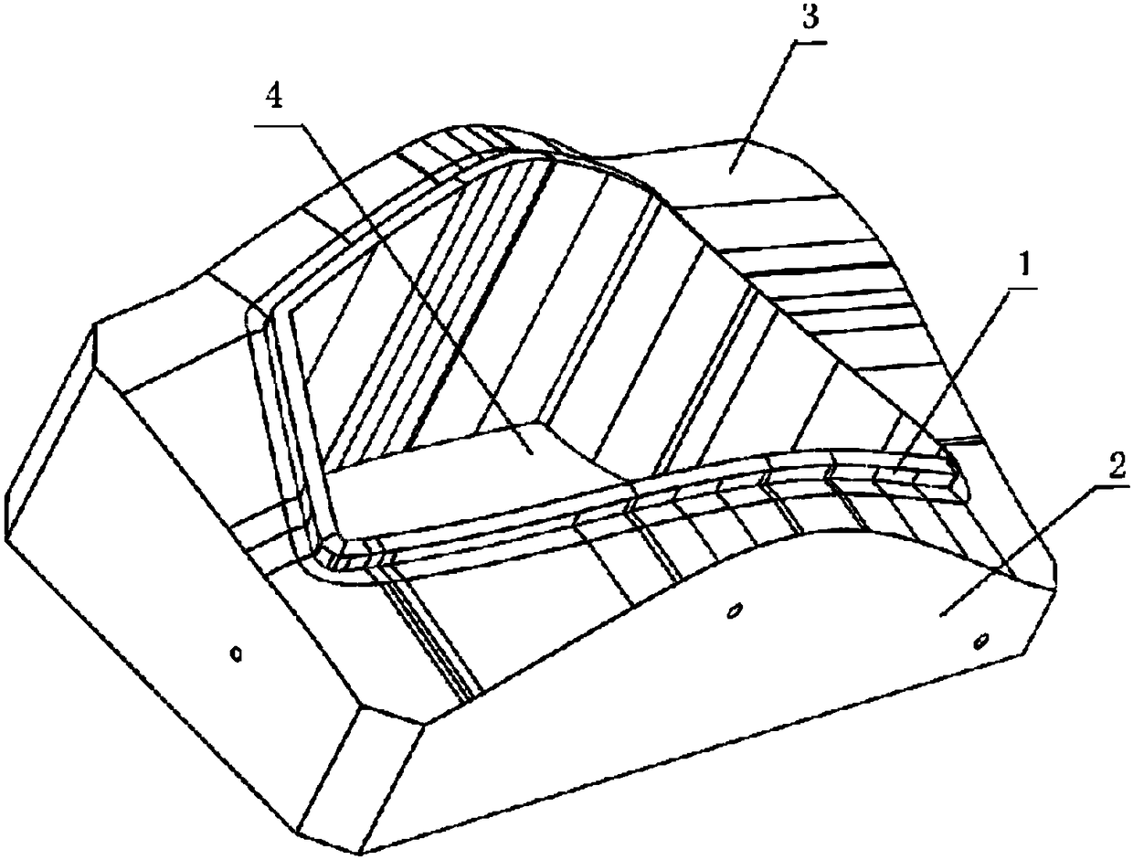
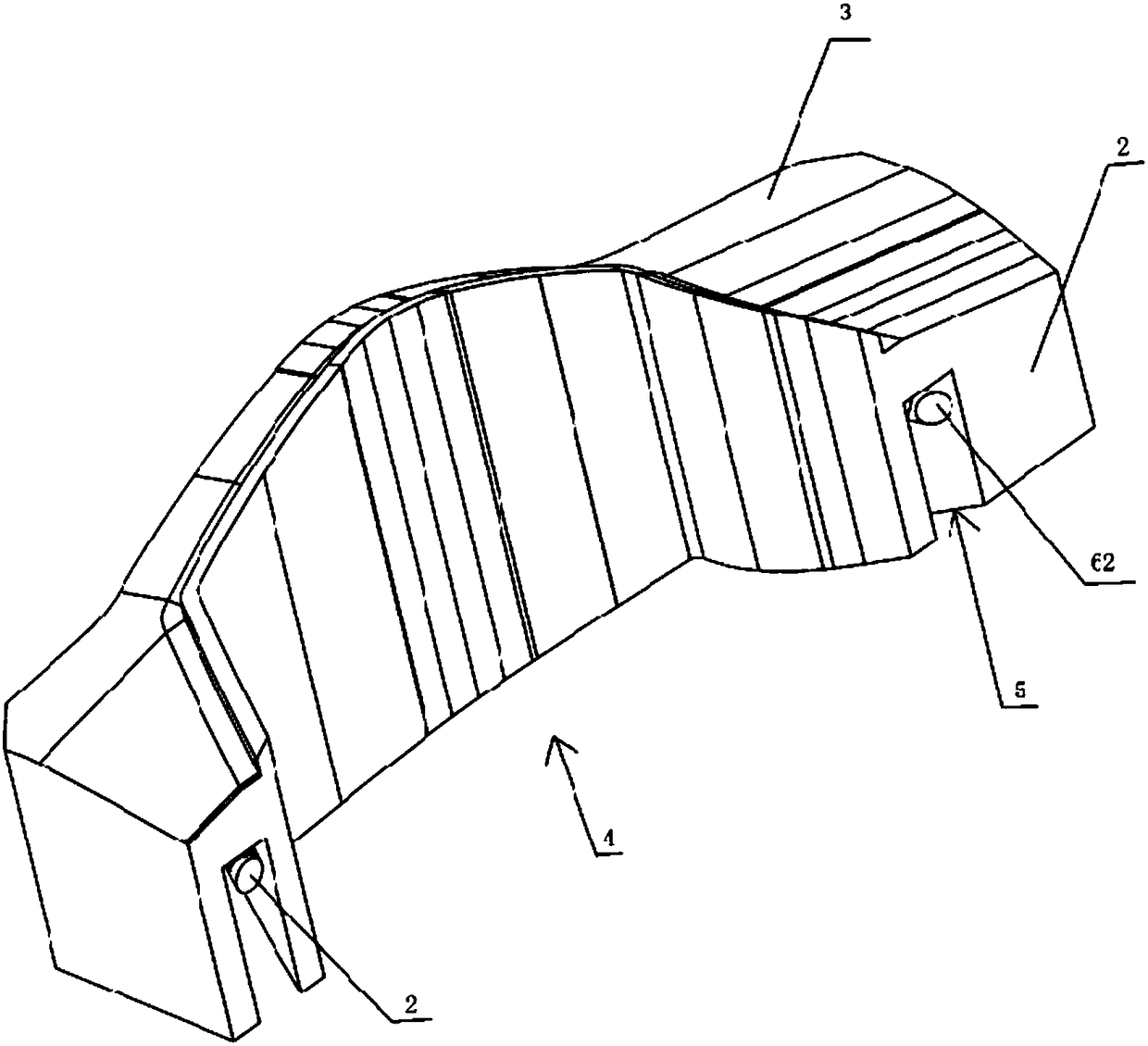
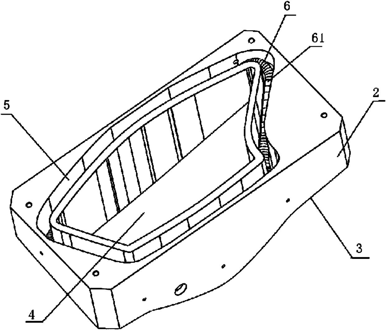
[0014] Such as figure 1 , 2 As shown in , 3, the hot plate mold for the manufacturing equipment of the car lamp shell includes an upper surface as a working surface 3 corresponding to the shape of the workpiece to be processed, and a mold seat 2 whose lower surface is the mounting surface, and a heating wire tube 6 is arranged in the mold seat 2 The heating wire tube 6 is composed of a whole heating wire 61 wound on an insulating support rod 6 made of prefabricated ceramic material, and the mounting surface of the mold base 2 is provided with a heating groove 5 for placing the heating wire tube 6 , The heating groove 5 corresponds to the outer contour of the welding rib 1 used when processing the workpiece, and the middle part of the mold holder 2 corresponds to a hollow cavity 4 within the contour range of the heating groove 5 to make the upp...


PUM


Abstract

The invention relates to the field of mechanical equipment, in particular to a hot plate mold for automobile lamp housing manufacturing equipment. The hot plate mold for automobile lamp housing manufacturing equipment comprises a mold base, the upper surface of which is a working face of a shape corresponding to a to-be-processed workpiece, wherein a heating device is arranged in the mold base; aheating groove for placing the heating device is formed in a mounting face of the mold base; the heating groove corresponds to the contour of the outer edge of a welding rib used for processing the workpiece; and a hollow cavity is formed in the contour range of the heating groove in the middle of the mold base, so that the upper surface and the lower surface of the mold base are connected through. The mold provided by the invention has the advantages of being simple to operate, low in manufacturing cost and good in using effect.

Description

technical field [0001] The invention relates to the field of mechanical equipment, in particular to a hot plate mold used in the production of car lamp shells. Background technique [0002] At present, hot plate molds are widely used in the production process of car lamp housings, especially the outer edge of the car lamp housing needs to be hot-pressed and welded to make the edge of the lamp housing thicker to increase strength. Of course, it is more often used in The outer cover of the shell and the edge of the inner cover need to be fused together by welding with welding ribs. In the prior art, the above-mentioned production is generally completed by adding welding ribs into the hot plate mold of the welding machine and hot pressing. Usually, the hot plate mold for making this type of car lamp housing is composed of an upper mold, a middle and upper mold, a middle and lower mold and The lower mold consists of four parts, among which the middle, upper and middle are the h...

Claims


Application Information

Patent Timeline
Patent Type & Authority Applications(China)
IPC IPC(8): B29C43/36B29C43/52B29L31/30
CPCB29C43/36B29C43/52B29L2031/7472
Inventor 罗云飞
Owner JIANGSU YEDI AUTOMOTIVE LIGHTING SYST
Why Eureka
Try Eureka