
Self-unloading crane

A crane and self-unloading technology, which is applied in the direction of hoisting device, lifting frame, etc., can solve the problems of high cost, uneconomical crane, low manufacturing cost of lifting equipment, etc., and achieve the effect of convenient use and low manufacturing cost

Pending Publication Date: 2018-07-17
赣榆区海头镇钦法电动车销售门市
View PDF9 Cites 3 Cited by
  • Summary
  • Abstract
  • Description
  • Claims
  • Application Information

AI Technical Summary

Problems solved by technology

[0002] Lifting equipment is a necessary handling equipment in the production field. When in use, the usual crane has a large lifting weight and high work efficiency. However, when lifting lighter goods, it is not cost-effective to use a conventional crane. Therefore, there is no lifting equipment that can easily lift goods and has low manufacturing cost.

Method used


Image

  • Self-unloading crane
  • Self-unloading crane
  • Self-unloading crane

Examples


Embodiment 1

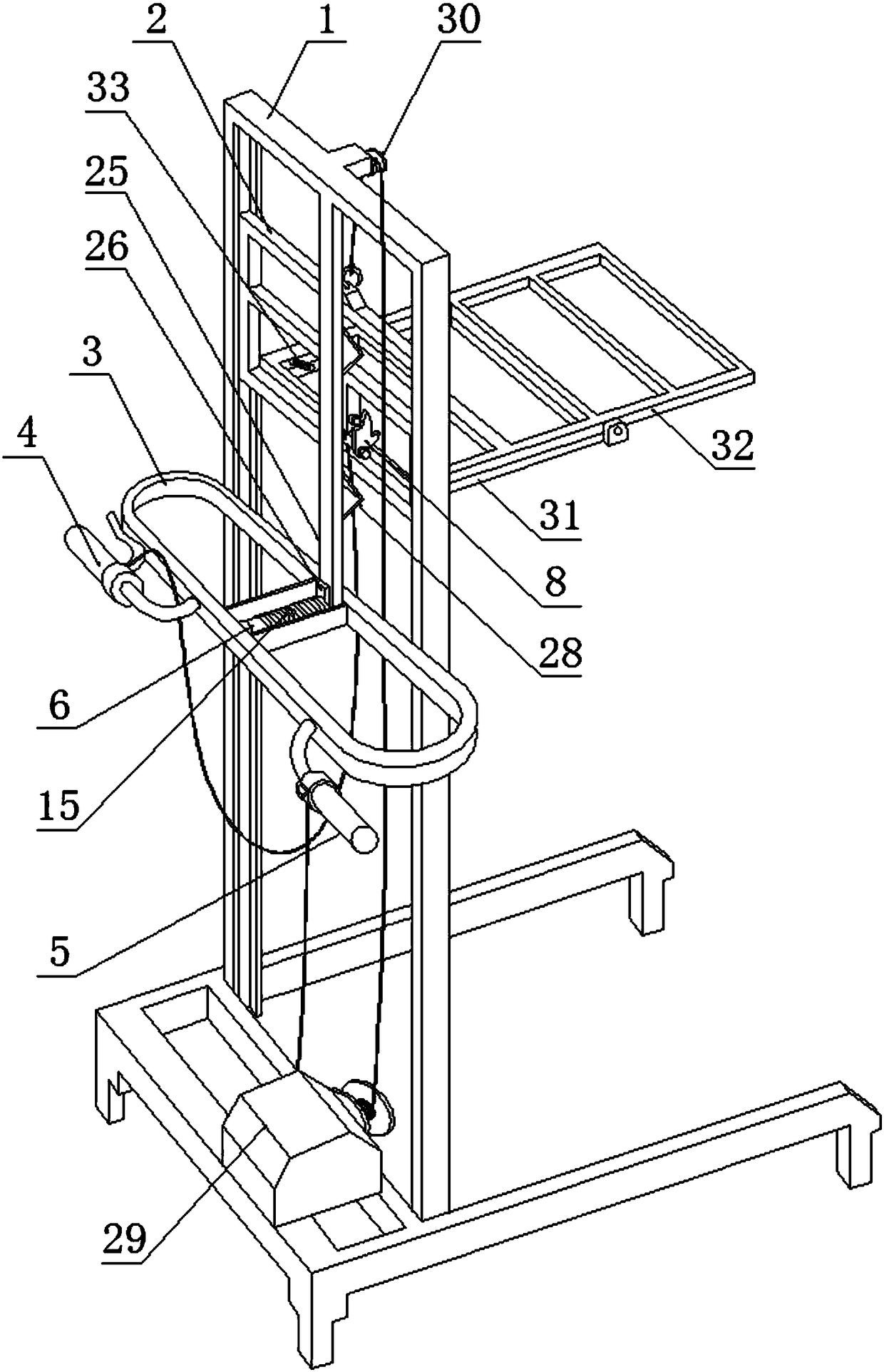
[0024] Example 1, reference figure 1 —3. A self-unloading crane, comprising a frame body 1, a lifting plate 2 is provided on the frame body 1, a dump mechanism is provided on the top of the lifting plate 2, and the frame body 1 is also provided There is a control mechanism mounting platform 3; the control mechanism mounting platform 3 includes a brake handle 4, a handle 5 for starting the lifting frame, and a cylindrical pin 6 fixed in the middle of the control mechanism mounting platform 3;

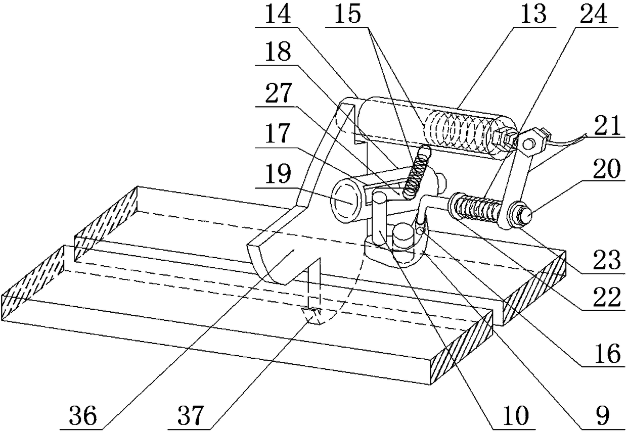
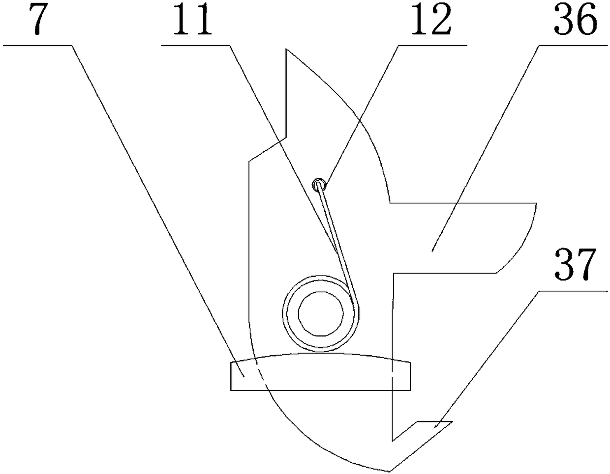
[0025] The self-unloading mechanism includes a rotating block mounting seat 7 fixedly mounted on the top of the aforementioned lifting plate 2, a rotating block 8 rotatably connected to the rotating block mounting seat 7, a shaft sleeve assembly fixedly mounted on the rotating block 8, and the aforementioned The pin shaft assembly used in conjunction with the rotating block 8, the rotating seat 9 and the pitch-adjusting assembly rotatably connected to the top end of the lifting plate 2; the ...

Embodiment 2

[0033] In the second embodiment, in the dump crane described in the first embodiment, the elastic element 15 adopts a compression spring.

Embodiment 3

[0034] In Embodiment 3, in the dump crane described in Embodiment 1, the rotating block return spring 11 is a torsion spring. After the rotating block 8 rotates, the resetting action can be realized by the rotating block return spring 11.


PUM


Abstract

The invention discloses a self-unloading crane. The self-unloading crane comprises a rack body. A lifting plate is arranged on the rack body. A self-unloading mechanism is arranged at the upper end ofthe lifting plate. A control mechanism installation platform is further arranged on the rack body and comprises a brake handle, a handle and a straight pin, wherein the handle is used for starting upa crane boom, and the straight pin is fixed to the middle of the control mechanism installation platform. The self-unloading mechanism comprises a rotary block installation base, a rotary block, a shaft sleeve assembly, a hinge pin assembly, a rotary base and a distance adjustment assembly, wherein the rotary block installation base is fixedly installed at the top end of a lifting plate, the rotary blocks is rotationally connected to the rotary block installation base, the shaft sleeve assembly is fixedly installed on the rotary block, the hinge pin assembly is used in cooperation with the rotary block, the rotary base is rotationally connected to the top end of the lifting plate, a limiting pin is arranged on the rotary base, a through hole is formed in the part, beside the limiting pin,of the rotary base, a rotary block reset spring is further arranged on the rotary block installation base, and a positioning hole is formed in the rotary block. The self-unloading crane is reasonablein design, convenient to operate for hoisting, and wide in application range.

Description

Technical field [0001] The invention relates to a lifting equipment, in particular to a self-unloading crane. Background technique [0002] Lifting equipment is a necessary handling equipment in the production field. When in use, ordinary cranes have heavy lifting weight and high work efficiency. However, when lifting light weight goods, it is not cost-effective to use conventional cranes. It is relatively high, so there is currently no lifting equipment that can easily carry goods and has a low manufacturing cost. Summary of the invention [0003] The technical problem to be solved by the present invention is to aim at the shortcomings of the prior art and provide a self-unloading hoisting frame with low manufacturing cost and convenient unloading. [0004] The technical problem to be solved by the present invention is achieved by the following technical solutions. A self-unloading crane includes a frame body, the frame body is provided with a lifting plate, and the top of the lif...

Claims


Application Information

Patent Timeline
Patent Type & Authority Applications(China)
IPC IPC(8): B66F7/04B66F7/28
CPCB66F7/04B66F7/28
Inventor 孙钦法
Owner 赣榆区海头镇钦法电动车销售门市
Learn More