Press roller structure

A technology of pressing rollers and scrapers, which is applied in the field of agricultural machinery, can solve the problems of insufficient pressure of the pressing rollers, damage of scrapers, lightening and deformation, etc., and achieve the effect of good pressure effect and good suppression effect

Inactive Publication Date: 2018-07-20
NANZHANG COUNTY HUASHENG MACHINERY MFG
View PDF1 Cites 3 Cited by
  • Summary
  • Abstract
  • Description
  • Claims
  • Application Information

AI Technical Summary

Problems solved by technology

[0004] In order to overcome the problems of insufficient pressure of the pressure roller in the pressure wheel of the seeder in the prior art, and the scraper will be damaged or lightened and deformed after a period of use, the present invention provides a structure of the pressure roller, including the pressure roller body and the The installation frame for installing the pressure roller body on the seeder, the installation frame is provided with a soil removal assembly for removing the soil on the surface of the pressure roller body, and the soil removal assembly includes a scraper plate and a scraper tight The upper end of the scraper plate is installed on the installation frame through the first connecting shaft, and the lower end is in contact with the surface of the pressure roller body. One end of the scraper fastening spring assembly is installed on the mounting frame through the second connecting shaft. The middle part of the scraper plate, the other end is installed on the installation frame through the third connecting shaft
[0005] The scraper plate and the scraper fastening spring assembly are used to form the soil removal assembly, and the scraper plate is pressed against the pressure roller through the scraper fastening spring assembly to offset the outward thrust of the pressure roller on the scraper plate, thereby effectively preventing the scraper from being Problems such as damage or lightening and deformation during use

Method used


Image

  • Press roller structure

Examples


Embodiment Construction

[0020] The present invention will be described in further detail below in conjunction with the embodiments and accompanying drawings. It should be understood that the specific embodiments described here are only used to explain the present invention, not to limit the present invention.

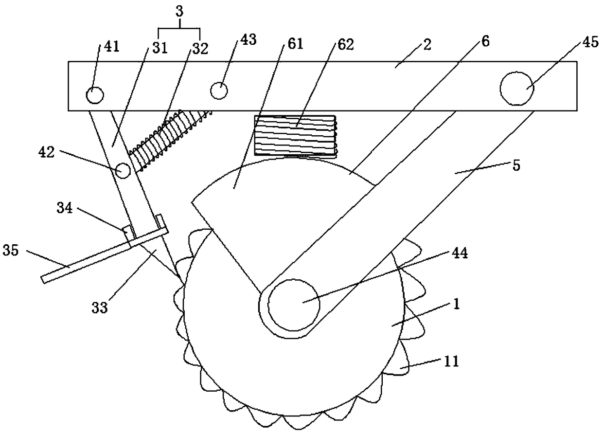
[0021] Such as figure 1 As shown, the structure of the pressure roller includes a pressure roller body 1 and an installation frame 2 for installing the pressure roller body 1 on the seeder, and the installation frame 2 is provided with a structure for cleaning the surface of the pressure roller body 1. The mud removal assembly 3 of the mud, the mud removal assembly 3 includes a scraper plate 31 and a scraper fastening spring assembly 32, the upper end of the scraper plate 31 is installed on the installation frame 2 through the first connecting shaft 41, and the lower end is connected to the One end of the scraper fastening spring assembly 32 is mounted on the middle of the scraper plate 31 th...


PUM


Abstract

The invention discloses a press roller structure, and belongs to the field of agricultural machinery. The structure comprises a press roller body and a mounting rack used for installing the press roller body on a sower, the mounting rack is provided with a soil removing assembly used for removing soil on the surface of the press roller body, the soil removing assembly comprises a scraper plate anda scraper fastening spring assembly, the upper end of the scraper plate is installed on the mounting rack through a first connecting shaft, the lower end of the scraper plate makes contact with the surface of the press roller body, one end of the scraper fastening spring assembly is installed in the middle of the scraper plate through a second connecting shaft, and the other end of the scraper fastening spring assembly is installed on the mounting rack through a third connecting shaft. The press roller structure has the advantages that the scraper plate and the scraper fastening spring assembly are adopted for forming the soil removing assembly, the pressure in the direction of the press roller structure is applied to the scraper plate through the scraper fastening spring assembly so as to counteract the outward pushing force of the press roller to the scraper plate, and then the problem that in the use process of the scraper plate, damage or lightening or deformation or the like occurs is effectively prevented.

Description

technical field [0001] The invention relates to the field of agricultural machinery, in particular to a pressure roller structure. Background technique [0002] An important part of the seeder is the pressure roller, whose main function is to suppress the soil after sowing to increase the density and firmness of the soil, so as to prevent the rapid loss of soil moisture, protect the soil moisture, maintain the ground temperature, and provide for the seeds to germinate and Emergence creates a suitable seedbed environment; in the current situation of large and accumulated rice stalks being returned to the field for mechanical sowing operations, it is even more necessary to do a good job of compacting and compacting after sowing, which is conducive to seed emergence and rooting. [0003] However, the currently used seeder pressing rollers will more or less stick to the soil during the pressing operation, and the staff need to stop the machine frequently to remove the clay manua...

Claims


Application Information

Patent Timeline
Patent Type & Authority Applications(China)
IPC IPC(8): A01B29/04A01B29/06
CPCA01B29/04A01B29/06
Inventor 简永超魏万兴冯华安
Owner NANZHANG COUNTY HUASHENG MACHINERY MFG
Why Eureka
Try Eureka