
Cutting blade and manufacturing method thereof

A cutting blade and blade technology, applied in the field of blades, can solve the problems of increasing the workload and psychological pressure of operators, unbalanced cutting blade weight, rough cutting surface, etc., achieve long-term stable cutting performance, prevent low strength, and solve weight imbalance Effect

Inactive Publication Date: 2018-07-20
宫电高周波设备(上海)有限公司
View PDF6 Cites 0 Cited by
  • Summary
  • Abstract
  • Description
  • Claims
  • Application Information

AI Technical Summary

Problems solved by technology

Also, when screen printing for finishing procedures, the weight of the ink may not be uniform across the surface of the base metal
[0004] Therefore, the weight of the manufactured cutting blade is likely to be unbalanced. When the cutting blade is installed on a cutting machine, for example, if the material to be cut is wood, the base metal will vibrate when rotating, and the vibration will be transmitted to the operator, which will increase the workload of the operator. and psychological pressure, and the cutting surface of the cut material is very rough due to vibration
In addition, the vibration acts on each cutting blade, which increases the burden on the blade itself during cutting, and the cutting edge (blade) of the cutting blade wears out quickly. At the same time, due to the vibration of the cutting blade, the main shaft of the cutting machine itself is also easily damaged.
Therefore, the cutting blade will increase the burden and psychological pressure of the operator due to vibration, and cannot ensure that the cutting operation can obtain a good cutting surface, and it is also difficult to obtain long-term stable cutting performance, etc.

Method used


Image

  • Cutting blade and manufacturing method thereof
  • Cutting blade and manufacturing method thereof
  • Cutting blade and manufacturing method thereof

Examples


Embodiment Construction

[0028] Embodiments of the present invention will be described in detail below based on the drawings.

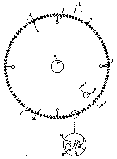
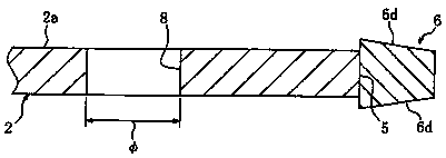
[0029] Figure 1~Figure 3 It is an embodiment of the dicing blade related to the present invention. Such as figure 1 As shown, the cutting blade 1 is a base metal 2 having a disc shape formed by pressing a carbon steel plate or the like, and a mounting hole 3 for mounting to a cutting machine (not shown) is formed at the center. On the outer peripheral edge portion 2a of the base metal 2, for example, a knife chamber 4 recessed in the direction of the mounting hole 3 and a blade fixing portion 5 formed by a step or a concave portion are provided at a certain interval in the circumferential direction, and the blades are fixed on each blade. The parts 5 are respectively brazed and fixed with inserts 6 made of, for example, cemented carbide.

[0030] The blade 6 is composed of an approximately L-shaped or approximately U-shaped fixed surface 6a in a plan view corresponding to...


PUM


Abstract

The invention provides a cutting blade and a manufacturing method thereof. Weight unbalance can be solved, burdens and mental stress of a worker are avoided, cutting work can obtain a good cutting face, and meanwhile, the long-term stable cutting function can be achieved. The cutting blade is characterized in that a circular-plate-shaped base body metal with a mounting hole in the central positionand blade fixing portions on the peripheral edge portion according to a certain interval and blade bodies fixed to the blade fixing portions of the base body metal are provided, and a method for arranging a certain-area opening and the like on the peripheral edge portion of the base body metal to adjust the weight unbalance according to the weight balance of the base body metal is provided. The opening is machined in a manner that the unbalance position and the deviation weight can be obtained on a balance measuring clamp under the vertical state in a manner of supporting the base body metalto freely rotate

Description

technical field [0001] The present invention relates to a blade mounted on the outer peripheral edge of a base metal, a cutting blade used for cutting wood and other materials to be cut, and a manufacturing method thereof. Background technique [0002] Conventionally, a cutting blade is a blade made of a cemented carbide alloy brazed and fixed to the outer peripheral edge portion of a disc-shaped base metal, as disclosed in Patent Document 1, for example. The cutting blade forms a plurality of knife chambers at certain intervals on the outer peripheral edge of the base metal, and at the same time, blade fixing parts are formed between the knife chambers, and the superhard alloy blades are respectively brazed and fixed on the blade fixing parts. As shown in Japanese Patent Application Laid-Open No. 2011-161819. [0003] However, in such cutting blades, the weight of the base metal may be unbalanced in the grinding and processing of the base metal, the grinding of the blade, ...

Claims


Application Information

Patent Timeline
IPC IPC(8): B23D79/00B23P15/28
CPCB23D79/00B23P15/28
Inventor 宫崎友良
Owner 宫电高周波设备(上海)有限公司
Learn More