Trajectory adjusting method and device
An adjustment method and trajectory technology, applied in auxiliary devices, auxiliary welding equipment, welding/cutting auxiliary equipment, etc., can solve the problems of waste of time and low efficiency, and achieve the effect of accurate adjustment
- Summary
- Abstract
- Description
- Claims
- Application Information
AI Technical Summary
Problems solved by technology
Method used
Image

Examples
Embodiment 1
[0026] In a trajectory generation process, multiple trajectory points will be generated. In the embodiment of the present invention, various generation tools can be used to generate the trajectory, for example, an industrial robot (including a mechanical arm and an end effector, and the end effector is used to perform the generation of trajectory point equipment), welding machine, before generating the trajectory, it is necessary to determine the parameters of the generated trajectory, which may include: the starting point of the generated trajectory, the end point of the generated trajectory, the total number of trajectory points, and the distance between the trajectory points , the direction of the generated track point, the coordinates of each track point, the attitude of each track point, and the orientation of the robot arm when generating the track point, etc.
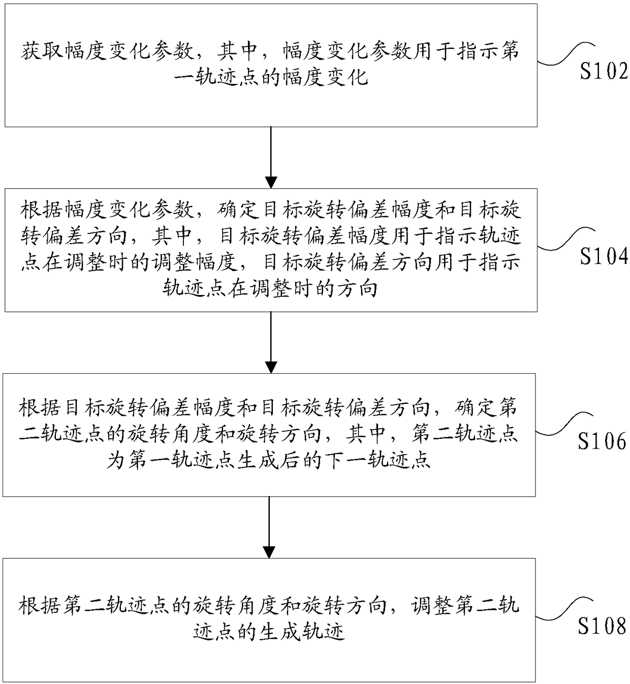
[0027] figure 1 is a flowchart of a trajectory adjustment method according to an embodiment of the present inv...
Embodiment 2
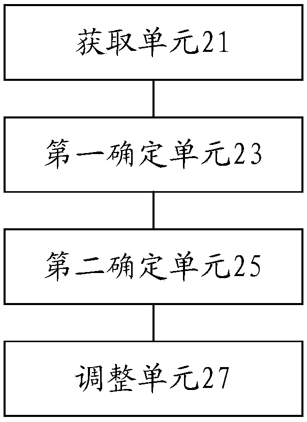
[0041] figure 2 is a schematic diagram of a trajectory adjustment device according to an embodiment of the present invention, such as figure 2 As shown, the device may include: an acquisition unit 21, configured to acquire an amplitude change parameter, wherein the amplitude change parameter is used to indicate the amplitude change of the first trajectory point; a first determination unit 23, configured to determine the target according to the amplitude change parameter The rotation deviation range and the target rotation deviation direction, wherein, the target rotation deviation range is used to indicate the adjustment range of the track point during adjustment, and the target rotation deviation direction is used to indicate the direction of the track point during adjustment; the second determination unit 25 is used to According to the target rotation deviation magnitude and the target rotation deviation direction, determine the rotation angle and rotation direction of the...
PUM
 Abstract
Description
Claims
Application Information