Electromagnetic oven manipulating device, electromagnetic oven and control method applied to manipulating device

A control device, induction cooker technology, applied in applications, household heating, household appliances, etc., can solve problems such as high cost, complex layout and wiring, and achieve the effect of reducing labor costs, workload, and complexity.

Inactive Publication Date: 2018-07-20
ZHEJIANG SHAOXING SUPOR DOMESTIC ELECTRICAL APPLIANCE CO LTD
View PDF4 Cites 2 Cited by
  • Summary
  • Abstract
  • Description
  • Claims
  • Application Information

AI Technical Summary

Problems solved by technology

[0005] The invention provides an electromagnetic cooker control device, an electromagnetic cooker and a control method applied to the control device, which are used to solve the problems of complex layout and wiring and high cost caused by too many buttons on the existing induction cooker panel

Method used


Image

  • Electromagnetic oven manipulating device, electromagnetic oven and control method applied to manipulating device
  • Electromagnetic oven manipulating device, electromagnetic oven and control method applied to manipulating device
  • Electromagnetic oven manipulating device, electromagnetic oven and control method applied to manipulating device

Examples


Embodiment 1

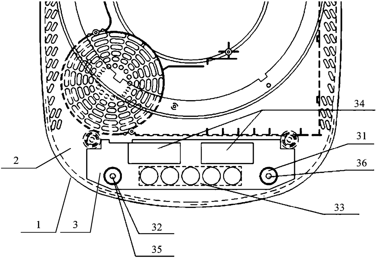
[0037] figure 1 It is a schematic structural diagram of an induction cooker control device provided in Embodiment 1 of the present invention. like figure 1 As shown, this embodiment provides a control device, which can be applied to an induction cooker. The induction cooker includes a housing 1 and a panel 2 arranged on the top of the housing 1 , and a control device is arranged on the panel 2 . The housing 1 is also provided with a controller (not shown in the figure), and the control device is electrically connected to the controller. The control device can receive the control instructions from the customer and send the control instructions to the controller, and control the control device according to the control instructions sent by the controller. The command displays the working status of the induction cooker on the control panel. A coil disc (not shown in the figure) is also arranged in the casing 1 for heating the pots on the panel 2 .

[0038] Specifically, the co...

Embodiment 2

[0046] This embodiment optimizes the control device of the induction cooker on the basis of the above-mentioned embodiment.

[0047] like figure 1 As shown, the above-mentioned timing / heating switch button 32 is integrated with a heating indicator 35 .

[0048] The heating indicator 35 is integrated in the timing / heating switch button 32 in a variety of ways. Specifically, it can be set according to the specific structure of the timing / heating switch button 32, so that the light emitted by the heating indicator 35 is located in the timing / heating switch. within the range covered by key 32.

[0049] Specifically, the heating indicator light 35 can be a light-emitting diode, and the color of the light emitted by the light-emitting diode can be white, red or yellow. The main body of the heating indicator light 35 is located in the timing / heating switch button 32, and the power supply end of the heating indicator light 35 is connected to the controller through a wire.

[0050] ...

Embodiment 3

[0058] In this embodiment, on the basis of the above-mentioned embodiment, the control device of the induction cooker is optimized, especially the realization mode of the function adjustment button group is further optimized.

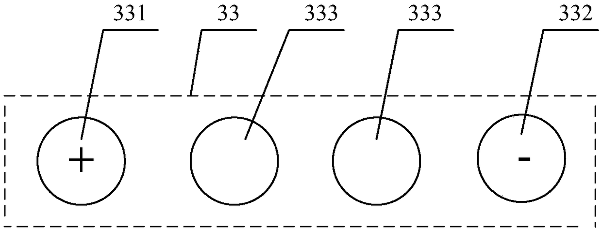
[0059] In this embodiment, the function of the above-mentioned function adjustment button group 33 is to adjust the heating power when the induction cooker is in the heating state, and to adjust the timing time in the timing state. The function adjustment button group 33 can be implemented in a variety of ways, for example, it can be implemented in the following ways:

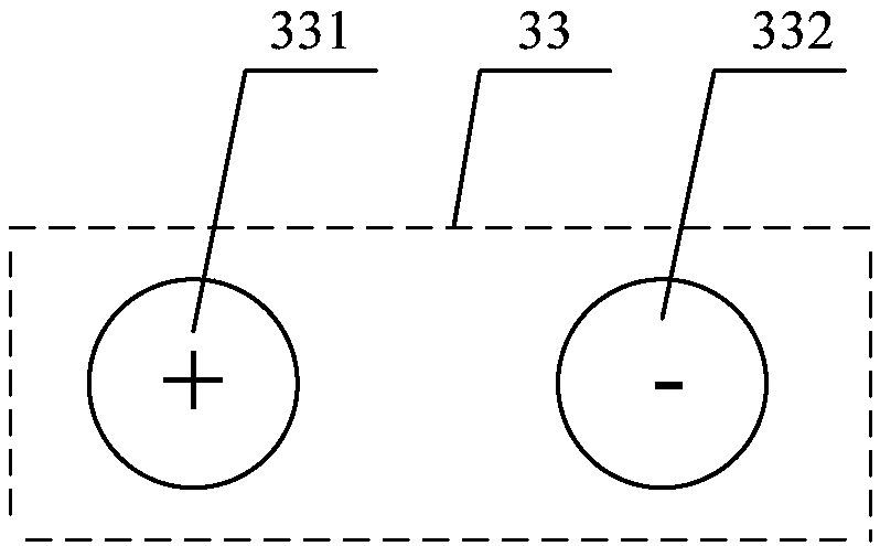
[0060] figure 2 The third embodiment of the present invention provides a schematic structural diagram of a function adjustment button group in an induction cooker control device Figure 1 . like figure 2 As shown, the function adjustment button group 33 includes: a first button 331 for increasing power or increasing time and a second button 332 for decreasing power or decreasing tim...


PUM


Abstract

The invention provides an electromagnetic oven manipulating device, an electromagnetic oven and a control method applied to the manipulating device. The manipulating device comprises a manipulating plate body arranged on an electromagnetic oven face plate, and the manipulating plate body is provided with a switch key, a timing/heating switching key, a function adjusting key set and a displaying device for displaying work parameters of the electromagnetic oven. According to the electromagnetic oven manipulating device, the electromagnetic oven and the control method applied to the manipulatingdevice, the problems that too many keys are arranged on an existing electromagnetic oven face plate, so that layout and wiring are complex, and the cost is high can be solved.

Description

technical field [0001] The invention relates to an induction cooker control technology, in particular to an induction cooker control device, an induction cooker and a control method applied to the control device. Background technique [0002] The induction cooker, also known as the induction cooker, uses the coil plate to be energized to generate electromagnetic waves. When the electromagnetic waves pass through the bottom of the iron pot, they are cut by the bottom of the pot to generate numerous small eddy currents, which promote the high-speed rotation of the iron atoms in the iron pot itself and generate collision and friction to generate heat. , to heat the food in the pot. The induction cooker mainly includes a casing and a panel arranged on the top of the casing, and the coil disc is arranged in the casing. [0003] There are usually multiple control buttons on the panel, such as: switch button, heating function button, timing button, power adjustment button, and coo...

Claims


Application Information

Patent Timeline
Patent Type & Authority Applications(China)
IPC IPC(8): F24C7/08
CPCF24C7/083
Inventor 刘凯王飞
Owner ZHEJIANG SHAOXING SUPOR DOMESTIC ELECTRICAL APPLIANCE CO LTD
Why Eureka
Try Eureka