Clamp and plate component assembly system with clamp

A fixture and plate-like technology, which is applied in the field of fixture and plate-like component assembly systems, can solve the problems of scattered parts, increased assembly time, and time-consuming assembly.

Active Publication Date: 2018-07-20
AU OPTRONICS CORP
View PDF5 Cites 5 Cited by
  • Summary
  • Abstract
  • Description
  • Claims
  • Application Information

AI Technical Summary

Problems solved by technology

The jig can slide on the frame. However, the jigs used in the existing solar modules need to be inserted from the outer end of the frame, which will consume a lot of assembly time for large-scale deployment.
In addition, the parts of the existing fixture are usually too scattered and can only be assembled on site with the frame, which will also increase the assembly time
Therefore, the structure of the existing solar modules still needs to be improved

Method used


Image

  • Clamp and plate component assembly system with clamp
  • Clamp and plate component assembly system with clamp
  • Clamp and plate component assembly system with clamp

Examples


Embodiment Construction

[0062] The technical solution of the present invention will be described in detail below in conjunction with the accompanying drawings and specific embodiments to further understand the purpose, solution and effect of the present invention, but it is not intended to limit the scope of protection of the appended claims of the present invention.

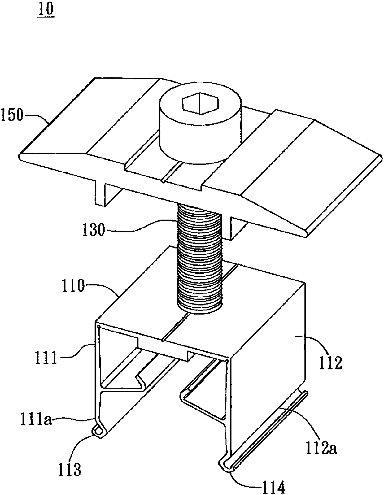
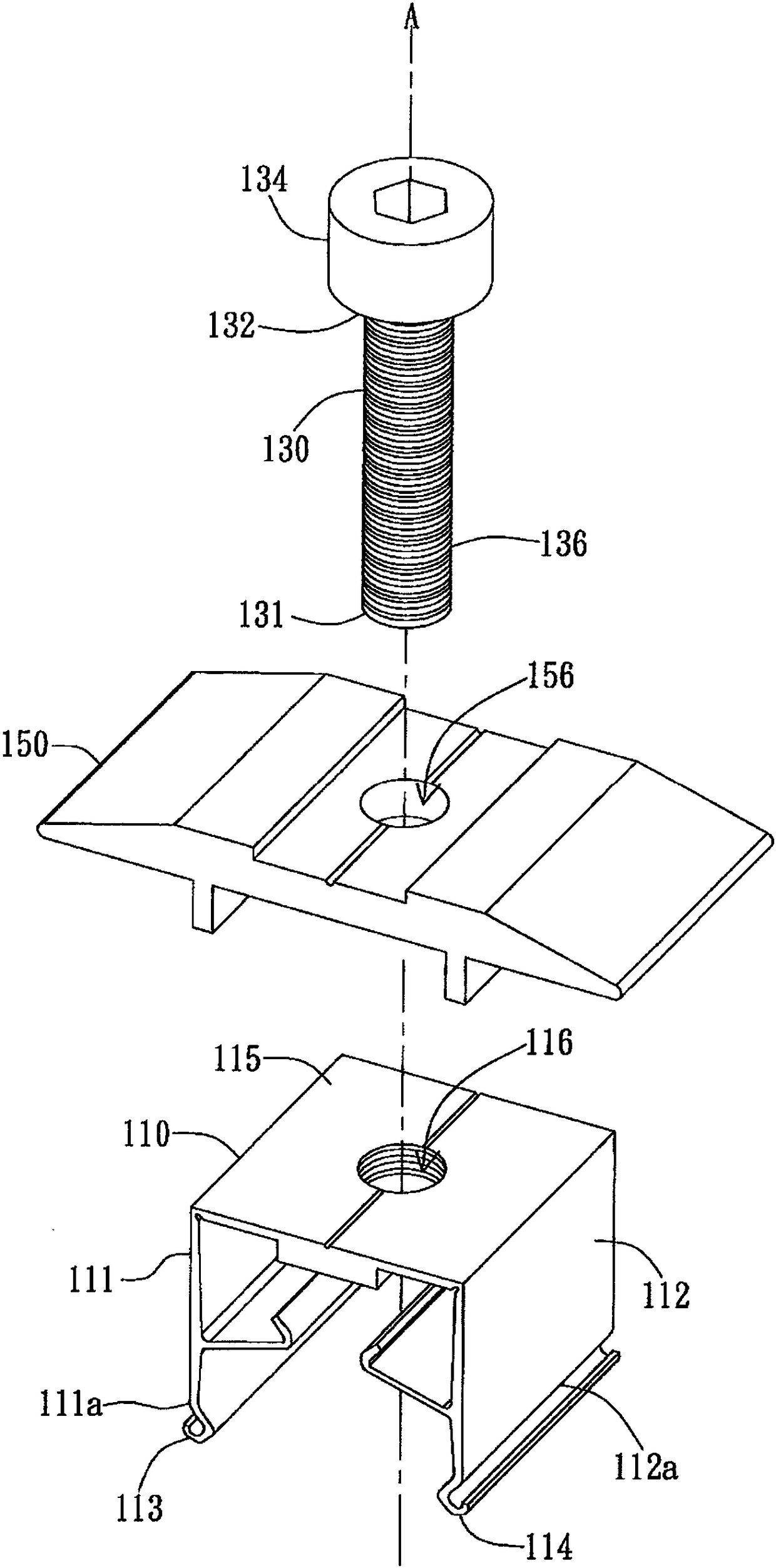
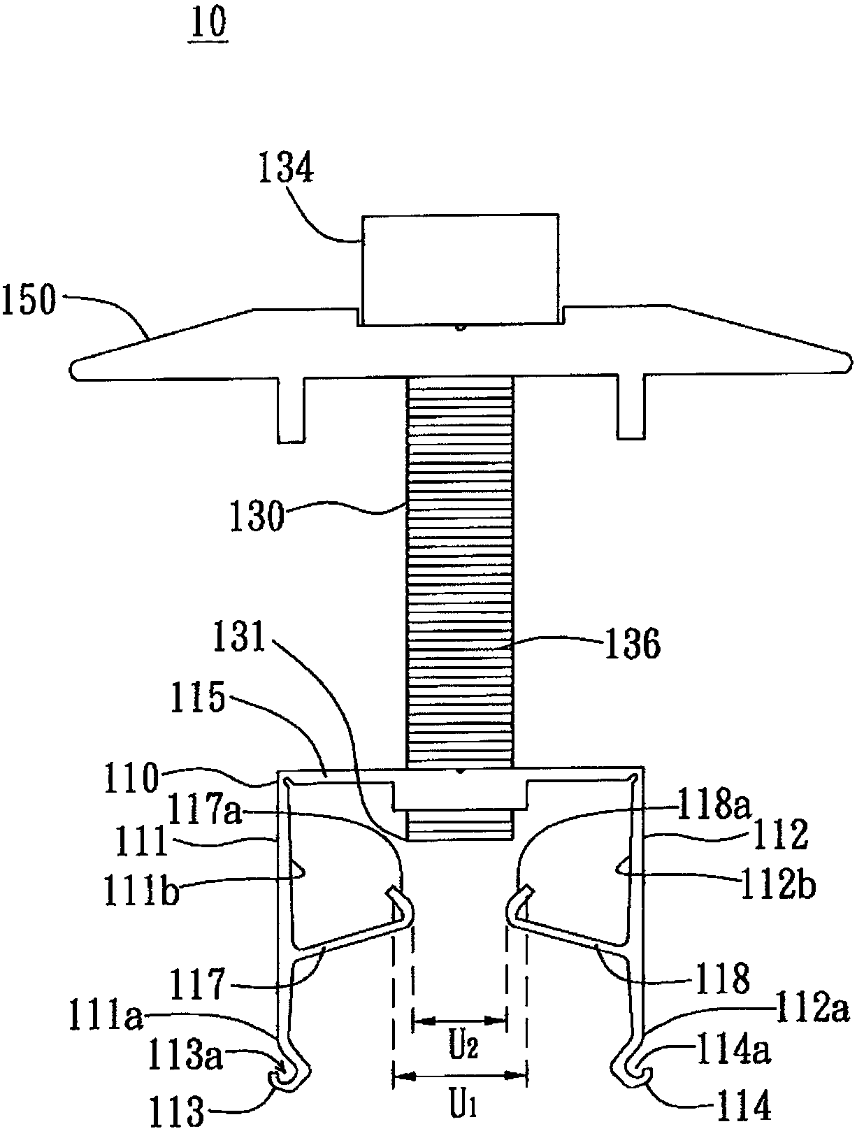
[0063] The invention provides a clamp for being arranged on a frame to clamp a plate-shaped component. The plate-shaped element is, for example, a solar panel, but not limited thereto. figure 1 It is a perspective view of an embodiment of the clamp 10 of the present invention. Such as figure 1 As shown, the clamp 10 includes a clamp seat 110 , a rod 130 , and a pressing block 150 . The holder 110 has a first branch wall 111 and a second branch wall 112 . The first branch wall 111 has a first free end 111a, and a first hook 113 is formed on the first free end 111a. The second branch wall 112 is opposite to the first branch wall 111 ...


PUM


Abstract

The invention discloses a clamp and a plate component assembly system with a clamp, and the clamp comprises a clamp seat, a rod member and a pressure block. The clamping seat has a first wall and a second wall; wherein the first wall has a first free end on which the first hook is formed. The second wall is disposed opposite the first wall and has a second free end opposite the first free end; anda second hook is formed on the second free end. The rod has a first end; the first end passes through the holder to move axially between the first wall and the second wall. The pressure block is disposed on the rod at the other side of the clamp opposite the first end; and is movable toward or away from the clamp. When the first end of the rod moves to the first position, the first end presses the first wall and / or the second wall to expand; when the first end of the rod moves to the second position, a gap is formed between the first end and the first wall as well as between the first end andthe second wall.

Description

technical field [0001] The present invention relates to a jig and a plate-shaped component assembly system; specifically, the present invention relates to a jig and a plate-shaped component assembly system that can be used in solar modules. Background technique [0002] Solar power generation is a technology in green power generation. The existing solar module installation method is to assemble the solar panel on the frame body through the assembly of the clamp and the frame body. The jig can slide on the frame. However, the jigs used in the existing solar modules need to be inserted from the outer end of the frame, which will consume a lot of assembly time for large-scale deployment. In addition, the parts of the existing fixture are usually too dispersed, and can only be assembled on site with the frame, which also increases the assembly time. Therefore, the structure of the existing solar module still needs to be improved. Contents of the invention [0003] An object...

Claims


Application Information

Patent Timeline
Patent Type & Authority Applications(China)
IPC IPC(8): H02S30/00
CPCH02S30/00Y02E10/50
Inventor 简培伦陈煜儒
Owner AU OPTRONICS CORP
Why Eureka
Try Eureka