Connection structure of sky train driving end
A connection structure and driving end technology, applied in the field of air rail, can solve the problems of large investment, inconvenient car body power supply, and high cost of air rail tracks
- Summary
- Abstract
- Description
- Claims
- Application Information
AI Technical Summary
Problems solved by technology
Method used
Image
Examples
Embodiment 1
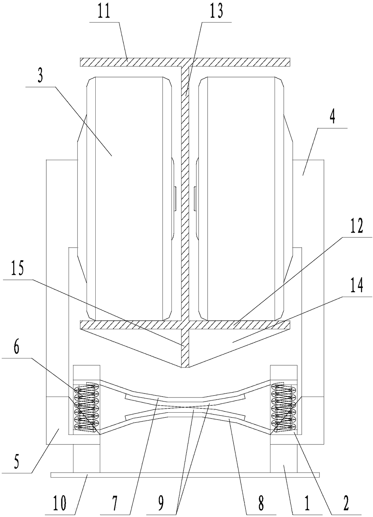
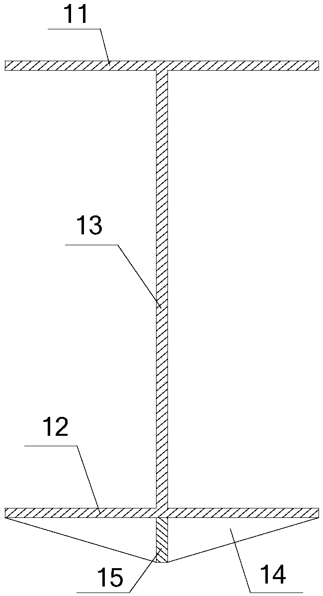
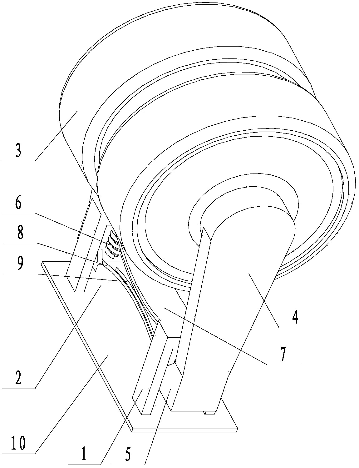
[0031] Such as Figure 1 to Figure 3 The connection structure of a driving end of empty iron shown includes a track and a power mechanism connected to the track. The track includes a top plate 11 and a bottom plate 12 facing each other in parallel. The top plate 11 is located directly above the bottom plate 12. Including a partition 13 fixed between the top board 11 and the bottom board 12, the partition board 13 is perpendicular to the top board 11 and the bottom board 12, and the top board 11 and the bottom board 12 are divided into left and right equal parts by the partition board 13; the bottom of the bottom board 12 is uniform A number of reinforcing ribs 14 are distributed; the power mechanism includes two hub motors 3 placed on the base plate 12, the two hub motors 3 are respectively located on both sides of the partition 13, and there is a gap between the two hub motors 3; 12 below the two mounting blocks 1 facing each other, the mounting blocks 1 are provided with thr...
Embodiment 2
[0033] Such as Figure 1 to Figure 3 In the connection structure of the driving end of empty iron shown, on the basis of Embodiment 1, a leaf spring is also connected between the two installation blocks 1 . The leaf spring includes an upper reed 7 and a lower reed 8 distributed up and down, and the upper reed 7 and the lower reed 8 face each other. The two ends of described upper reed 7 are respectively fixed on the top surface of two through holes 2, and the two ends of described lower reed 8 are respectively fixed on two bearing blocks 5; Upper reed 7, lower reed 8 link to each other. Both the bottom of the upper reed 7 and the top of the lower reed 8 are provided with wear strips 9 . The upper reed 7 and the lower reed 8 are arc-shaped plates, the upper reed 7 protrudes toward the lower reed 8, and the lower reed 8 protrudes toward the upper reed 7 direction. It also includes a suspension plate 10 fixedly connected under the two installation blocks 1, and the suspension ...
PUM
 Abstract
Description
Claims
Application Information
 - R&D
- Intellectual Property
- Life Sciences
- Materials
- Tech Scout
- Unparalleled Data Quality
- Higher Quality Content
- 60% Fewer Hallucinations
Browse by: Latest US Patents, China's latest patents, Technical Efficacy Thesaurus, Application Domain, Technology Topic, Popular Technical Reports.
© 2025 PatSnap. All rights reserved.Legal|Privacy policy|Modern Slavery Act Transparency Statement|Sitemap|About US| Contact US: help@patsnap.com


