
Adjustable pressing wheel assembly of road roller and adjustment method of adjustable pressing wheel assembly

A road roller and adjustable technology, applied in the field of construction machinery, can solve the problems of high maintenance cost, easy retraction under force, and failure to achieve the effect, and achieve the effect of improving construction quality, increasing quantity and scale

Inactive Publication Date: 2018-07-24
XINCHANG COUNTY YINGDAO TECH CO LTD
View PDF1 Cites 0 Cited by
  • Summary
  • Abstract
  • Description
  • Claims
  • Application Information

AI Technical Summary

Problems solved by technology

[0004] 1. Since its working process is to press holes in the soil, and then flatten the soil, it is equivalent to flattening the soil in the last step, and in order to make the pressure wheel move forward or backward, it can realize the function of forming air holes on the soil. By setting two magnetic blocks 2, the air outlet rods at the front and rear of the pressure wheel can extend out of the pressure wheel to press holes in the soil, although it is possible to form air holes on the soil when the pressure wheel advances or retreats. But the last step is always to press the air outlet rods in the front and rear of the pressure wheel to press holes on the soil, not to flatten the soil. It is equivalent to pressing the air outlet on the road surface and then passing through the outer wall of the pressure wheel to flatten it. After flattening, it will be flattened again. The air outlet rod at the rear presses out the air outlet, so the intended function cannot be realized, and the road surface quality will be affected instead;
[0005] 2. The skateboard is always located vertically below the action of gravity, so the contact surface between the pressure roller and the road surface is the lowest surface of the pressure roller in the vertical direction, so the pressure roller assembly is only suitable for horizontal road surfaces. The contact surface between the slope road surface and the pressure roller is not the vertically lower surface of the pressure roller, so the air outlet rod at the position of the pressure roller in contact with the slope road surface will protrude from the outer wall of the pressure roller, which cannot compact the ground, but will affect the flatness of the ground instead. Under certain circumstances, the air outlet rod protruding from the outer wall of the pressure roller may not necessarily penetrate into the soil, so the intended effect cannot be achieved.
[0006] 3. Magnetic block 2 cooperates with magnetic block 1 to repel each other, so that the air outlet rod extends out of the outer wall of the pressure wheel, so the structure of the extended air outlet rod is unstable, and it is easy to be retracted under force during the process of entering the soil, which cannot achieve a good performance. Effect
[0008] 5. The air outlet rod is damaged and cannot be disassembled and replaced, and the maintenance cost is high

Method used


Image

  • Adjustable pressing wheel assembly of road roller and adjustment method of adjustable pressing wheel assembly
  • Adjustable pressing wheel assembly of road roller and adjustment method of adjustable pressing wheel assembly
  • Adjustable pressing wheel assembly of road roller and adjustment method of adjustable pressing wheel assembly

Examples


Embodiment Construction

[0048] The following are specific embodiments of the present invention and in conjunction with the accompanying drawings, the technical solutions of the present invention are further described, but the present invention is not limited to these embodiments.

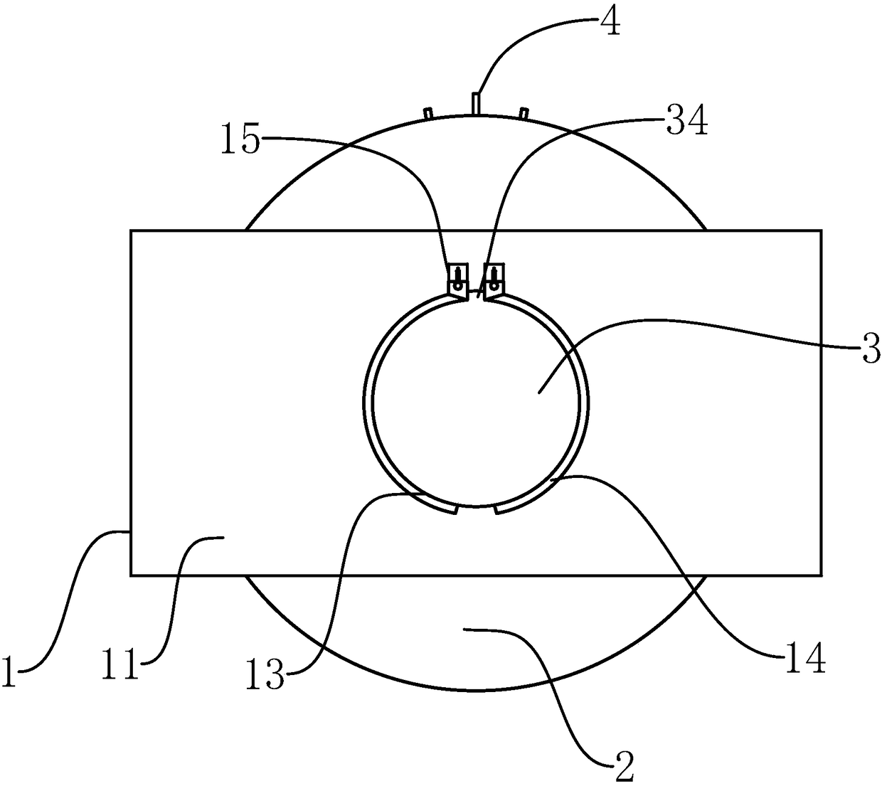
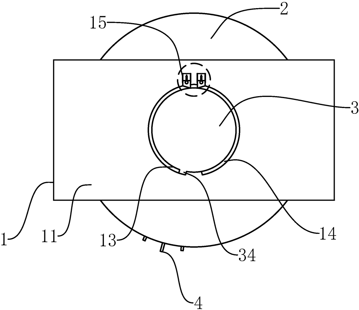
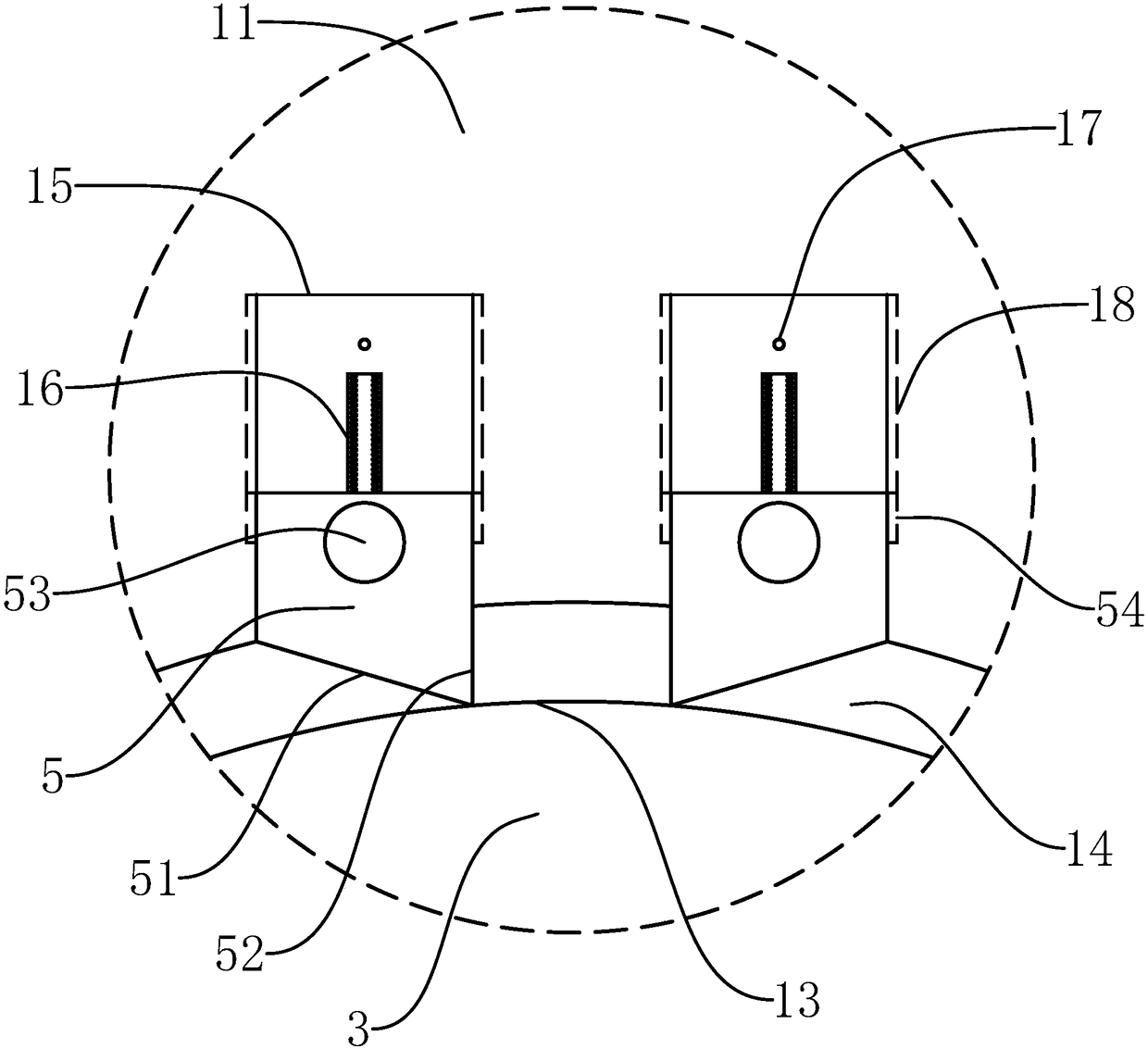
[0049] Such as Figure 1-7 As shown, an adjustable pressure roller assembly of the present invention includes a vehicle frame 1 and a cylindrical pressure roller 2 arranged on the vehicle frame 1. The pressure roller 2 is coaxially provided with a shaft hole 21, and also includes a matching activity piercing In the wheel shaft 3 in the shaft hole 21, the outer wall of the wheel shaft 3 is coaxially provided with a number of annular rod grooves 31, the groove walls on both sides of the rod groove 31 are perpendicular to the axis of the wheel shaft 3, and the pressure wheel 2 is provided with some rod holes 22 radially. The rod holes 22 are uniformly distributed at equal angles along the circumference of the pressure roller ...


PUM


Abstract

The invention provides an adjustable pressing wheel assembly of a road roller and an adjustment method of the adjustable pressing wheel assembly and belongs to the field of engineering machinery, aiming at solving the problem that the construction effect of an existing road roller is poor. The adjustable pressing wheel assembly of the road roller comprises a frame and a pressing wheel provided with a shaft hole, and further comprises a wheel shaft penetrating into the shaft hole; a rod groove is formed in an outer wall of the wheel shaft; a rod hole is formed in the pressing wheel; the adjustable pressing wheel assembly further comprises an air outlet rod penetrating into the rod hole; a main sliding groove and a secondary sliding groove are formed in a groove wall of the rod groove; a sliding block is fixed at the rear end of the air outlet rod; the frame comprises a main frame plate provided with a wheel hole and a secondary frame plate with a wheel groove; the rear end of the wheelshaft is connected into the wheel groove and the front end of the wheel shaft penetrates into the wheel hole; a limiting groove is formed in the outer side of the main frame plate; a limiting block isfixed on an outer wall of the wheel shaft; a locking groove with a locking block is formed in a groove wall of the limiting groove; an adjusting groove is formed in a groove bottom of the locking groove; the adjustable pressing wheel assembly further comprises an adjusting block located in the adjusting groove; a compression spring is arranged in the adjusting groove; the locking block is connected with a spring bolt; the adjusting block is provided with a front bolt groove and a rear bolt groove is formed in the groove bottom of the locking groove. By adopting the pressing wheel, the construction quality can be improved.

Description

technical field [0001] The invention belongs to the technical field of engineering machinery, and relates to an adjustable pressure wheel assembly of a road roller and an adjustment method thereof. Background technique [0002] As construction machinery, road rollers can roll sandy, semi-cohesive and cohesive soils, subgrade stabilized soils, and asphalt concrete road surfaces, and are widely used in filling and compacting operations for large-scale engineering projects such as roads, railways, airport runways, dams, and stadiums. . [0003] Existing road rollers can only use rollers to compact the surface of the land. Due to the limited extrusion force, the air inside the land cannot be fully squeezed out, and the compaction effect is poor. The existing application number is "201610319604.1", and the invention name is "a high-efficiency exhaust road bridge roller roller assembly". Cooperate with the magnetic block on the air outlet rod to repel each other to form air outl...

Claims


Application Information

Patent Timeline
Patent Type & Authority Applications(China)
IPC IPC(8): E01C19/23
CPCE01C19/236
Inventor 张云生
Owner XINCHANG COUNTY YINGDAO TECH CO LTD
Learn More