Wing structure of cross-flow fan

A cross-flow, fin technology, applied in the field of fin structure, can solve the problems of inability to meet user needs, high noise of air conditioner indoor unit, prominent rotation noise, etc., and achieve simple and reasonable structure, increased air volume, and low working noise. Effect

Pending Publication Date: 2018-07-24
GUANGDONG SUNWILL PRECISING PLASITC CO LTD
View PDF1 Cites 1 Cited by
  • Summary
  • Abstract
  • Description
  • Claims
  • Application Information

AI Technical Summary

Problems solved by technology

However, the fan blades of this structure are made of a single-section circular arc, and when the fan blade is working, it is a single-section circular arc under pressure, and there is no buffer section when the airflow enters the blade grid, r

Method used


Image

  • Wing structure of cross-flow fan

Examples


Embodiment Construction

[0013] The present invention will be further described below in conjunction with the accompanying drawings and embodiments.

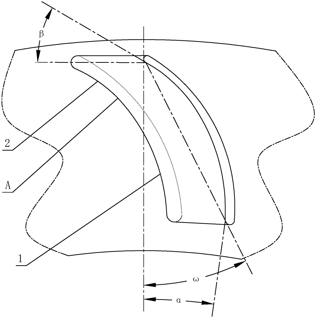
[0014] see figure 1 , the vane structure of this cross-flow fan, the pressure surface of the vane is composed of two arcs, which are the inner edge segment 1 and the outer edge segment 2 respectively; the turning point A is formed between the inner edge segment 1 and the outer edge segment 2, The turning point A is formed at a position 27% away from the chord length from the outer peripheral end of the chord; the arc radius ratio of the outer edge section 2 and the inner edge section 1 is 1:1.35±0.1.

[0015] Applied to the cross-flow fan of the conventional two-row tube indoor unit, the number of fins is 31.

[0016] Among them, during the operation of the cross-flow fan, the airflow passes through the cascade twice, and after the first time the cascade does work, the airflow velocity increases significantly when the airflow enters the cascade for the...


PUM


Abstract

The invention discloses a wing structure of a cross-flow fan. A pressure surface of a wing consists of two sections of arcs: an inner edge section and an outer edge section; a turning point is formedbetween the inner edge section and the outer edge section, and is formed at the peripheral end of a wing chord from a wing chord length by 27%; and the arc radius ratio value of the outer edge sectionand the inner edge section is 1: 1.35+-0.1. Through improvement of the structure, air currents firstly pass through 73% of the inner edge section during working; the pressing radius of the section islarger, the acting capacity is lower, and the buffering and rectifying effects are mainly achieved; the inner edge section is also called as a buffer section; then, the air currents pass through 27%of the outer edge section; the pressing radius of the section is lower, the acting capacity is higher, and main acting tasks are finished; the section is also call as an acting section; as an evaporator of an indoor unit of a conventional air conditioner adopts two rows of pipes, the overall resistance is lower; and as the cross-flow fan needs lower acting capacity, the buffer section of cross-flow blades can be enlarged as far as possible, the noise quality of the cross-flow fan is improved, and the practicability is high.

Description

technical field [0001] The invention relates to a vane structure of a cross-flow fan. Background technique [0002] Chinese patent literature number is CN2402847Y, discloses a kind of cross-flow fan of air conditioner on October 25, 2000, and it comprises blade and flange plate, and a plurality of blades are arranged to form cylindrical shape along the circumference of flange plate, and the shaft of blade and this cylinder The blades form a certain included angle, and the blades are not equidistantly distributed along the circumference of the flange. It is said that the structure has an even number of flanges to cut the blades into an odd number of small fans in the axial direction. It is parallel to the axial direction of the fan, which can realize the effect of concentrated wind force, lengthened wind distance and increased air volume. However, the fan blades of this structure are made of a single-section circular arc, and when the fan blade is working, it is a single-se...

Claims


Application Information

Patent Timeline
IPC IPC(8): F04D29/26F04D29/66
CPCF04D29/30F04D29/666
Inventor 毛军祥叶涛杨宇
Owner GUANGDONG SUNWILL PRECISING PLASITC CO LTD
Why Eureka
Try Eureka