
Electronic expansion valve

A technology of electronic expansion valve and valve needle, which is applied in the direction of lift valve, valve device, valve details, etc. It can solve the problems of valve port 51' leakage, contact surface wear, and poor valve performance, so as to improve reliability and reduce wear , The effect of reducing the amount of wear

Active Publication Date: 2018-07-24
ZHEJIANG SANHUA COMMERCIAL REFRIGERATION CO LTD
View PDF5 Cites 12 Cited by
  • Summary
  • Abstract
  • Description
  • Claims
  • Application Information

AI Technical Summary

Problems solved by technology

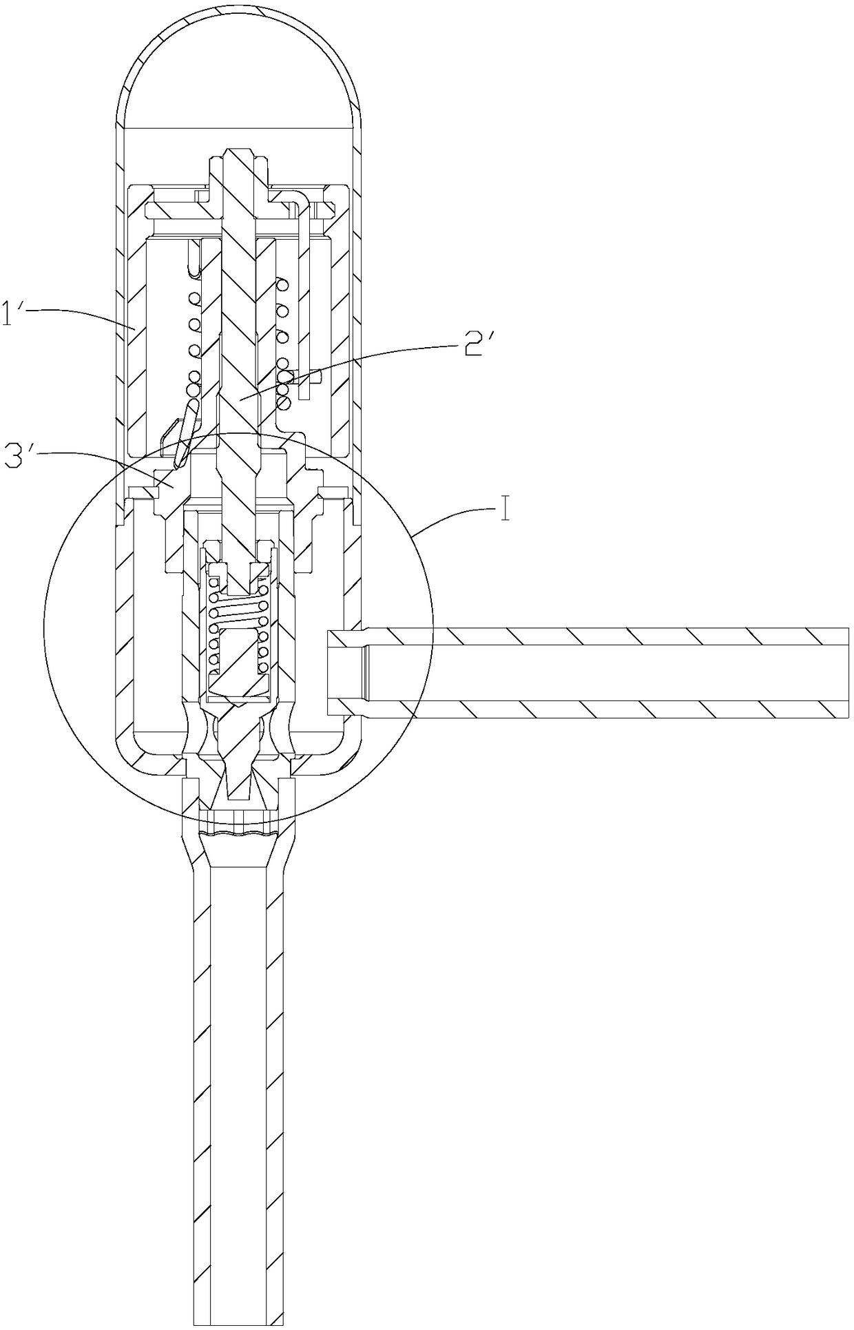
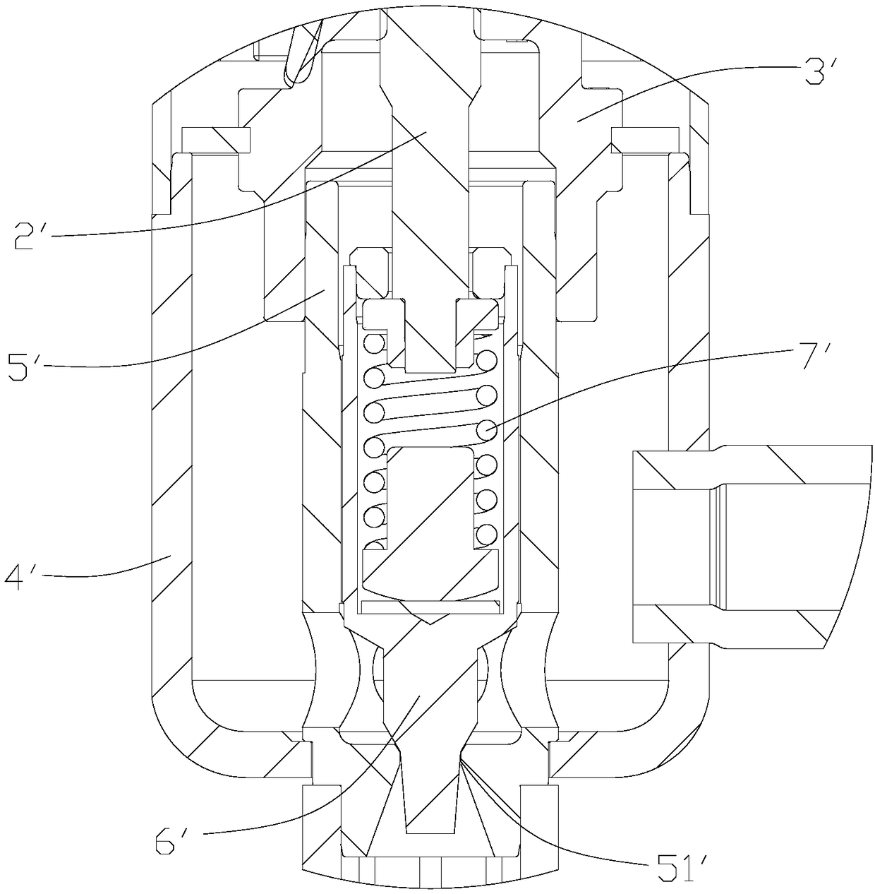
[0008] Since the valve needle 6' is located at the valve port 51' until the valve needle 6' is fully pushed to the valve port 51', the contact position between the valve needle 6' and the valve port 51' will always slide and rotate. , causing the contact surfaces of the two to be worn, especially in the case of repeated movements of the valve needle 6', the wear of the contact surface between the valve needle 6' and the valve port 51' will be further aggravated, causing the valve port 51' to be fully closed. The phenomenon of leakage under the state, resulting in poor valve performance

Method used


Image

  • Electronic expansion valve
  • Electronic expansion valve
  • Electronic expansion valve

Examples


Embodiment 1

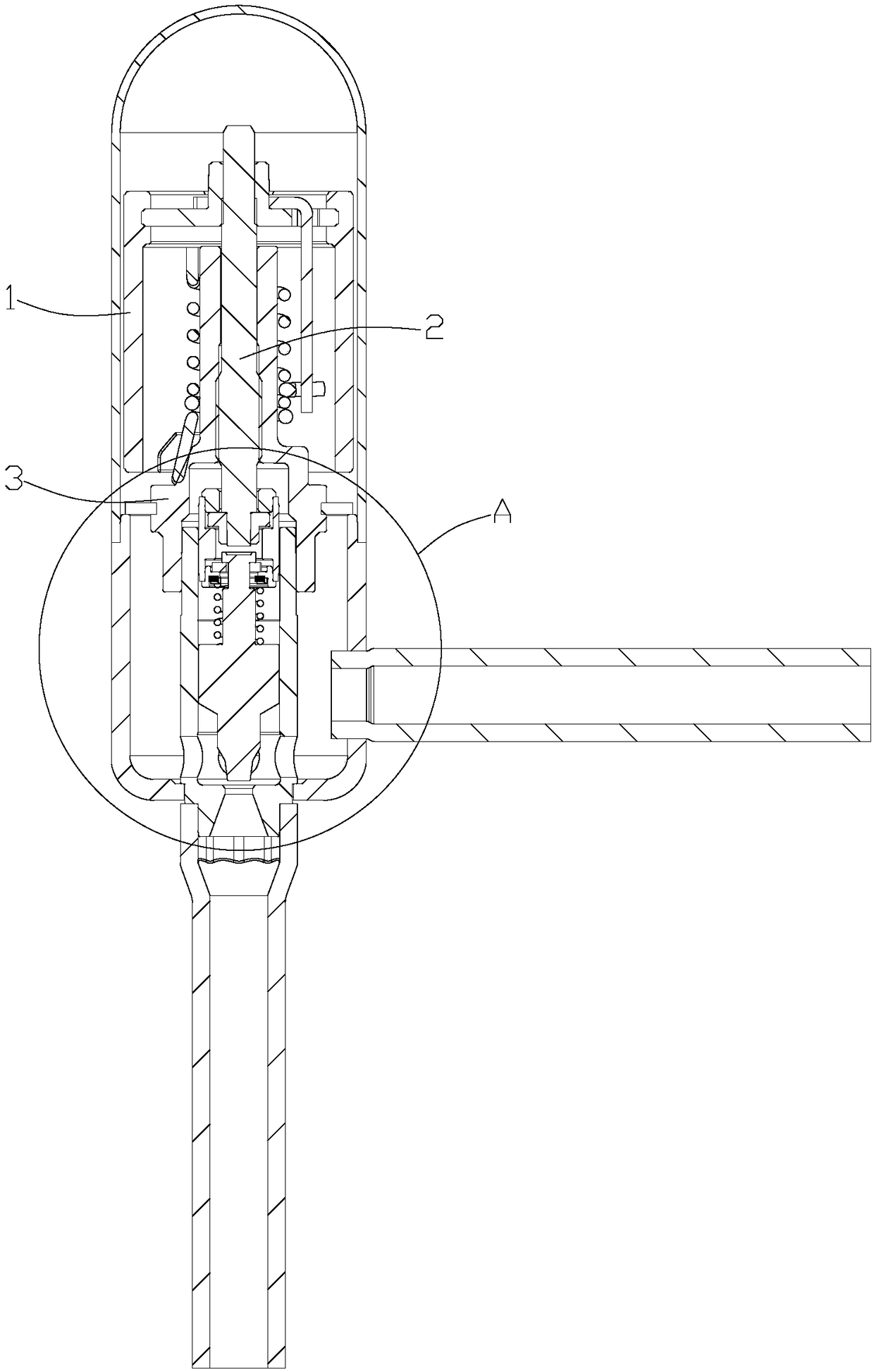
[0114] Please refer to image 3 and Figure 4 , image 3 It is a schematic cross-sectional view of the first embodiment of the electronic expansion valve provided by the present invention; Figure 4 for image 3 Partial enlarged view of part A in the middle.

[0115] in, image 3 The electronic expansion valve is shown open.

[0116] In this embodiment, the rotor 2 of the motor of the electronic expansion valve can rotate and drive the externally threaded shaft 2, and the externally threaded portion of the externally threaded shaft 2 is threadedly engaged with the internally threaded hole of the internally threaded part 3, wherein the internally threaded file 3 is fixed on The upper end of the valve seat 4; the lower end of the externally threaded shaft 2 is also connected with a valve needle 6a.

[0117] When the motor rotates, its rotor 2 can drive the externally threaded shaft 2 to rotate. At the same time, due to the thread engagement between the externally threaded ...

Embodiment 2

[0156] Please refer to Figure 8 and Figure 9 , Figure 8 It is a schematic cross-sectional view of the second embodiment of the electronic expansion valve provided by the present invention; Figure 9 for Figure 8 Partial enlarged view of part B in middle.

[0157] in, Figure 8 The electronic expansion valve is shown open.

[0158] In this embodiment, the externally threaded shaft 2 is connected to the valve needle 6b through a connecting piece 8b.

[0159] Wherein, the upper end of the connecting piece 8b has a first face facing downward, and the lower end of the externally threaded shaft 2 is provided with a first engaging member 9b, and the first engaging member 9b can be engaged with the first face so that the external thread The shaft 2 suspends and supports the connecting piece 8b; in addition, the first engaging piece 9b can also move relative to the connecting piece 8b along the axis direction.

[0160] The lower end of the connecting piece 8b has an upward s...

Embodiment 3

[0193] Please refer to Figure 13 and Figure 14 , Figure 13 It is a schematic cross-sectional view of the third embodiment of the electronic expansion valve provided by the present invention; Figure 14 for Figure 13 Partial enlarged view of part C in middle.

[0194] in, Figure 13 The electronic expansion valve is shown open.

[0195] In this embodiment, the externally threaded shaft 2 is connected to the valve needle 6c through a connecting piece 8c.

[0196] Wherein, the upper end of the connecting piece 8c has a first face facing downward, and the lower end of the externally threaded shaft 2 is provided with a first engaging member 9c, the first engaging member 9c can be engaged with the first face, so that the external thread The shaft 2 is suspended from the support connection 9c.

[0197] The connecting part 8c also has a limiting part located under the first face, and the first engaging part 9c can also move relative to the connecting part 8c along the axis ...


PUM


Abstract

The invention discloses an electronic expansion valve. The electronic expansion valve comprises a valve seat, a valve needle, an external threaded shaft, a connecting piece and a compression spring, wherein the compression spring is installed outside the connecting piece; both ends of the connecting piece are respectively connected with the external threaded shaft and the valve needle, and the compression spring is located between the external threaded shaft and the valve needle and is configured, so that the connecting piece can be driven to move in an axial direction by the external threadedshaft, the external threaded shaft and the valve needle can relatively move in the axial direction, when a valve port is in the early stage of the full-closed state, spring force which is used for pushing the valve needle to the valve port cannot be generated by the compression spring, and when the valve port is in the late stage of the full-closed state, elastic load which is used for closing the valve is generated on the valve needle by the compression spring; the early stage is from the beginning of closing the valve port by the valve needle until the external threaded shaft moves for a preset value in the valve closing direction relative to the valve needle; and the late stage is that the external threaded shaft moves for more than the preset value in the valve closing direction relative to the valve needle. According to the electronic expansion valve, the wear of the valve needle and the valve port can be reduced, so that the valve port is prevented from leaking when the valve port is fully closed.

Description

technical field [0001] The invention relates to the technical field of flow regulating valves, in particular to an electronic expansion valve. Background technique [0002] As an important part of the refrigeration system, the electronic expansion valve is widely used in large-scale refrigeration units, large-scale cold storage, supermarket freezers, etc. [0003] Please refer to Figure 1-2 , figure 1 It is a structural schematic diagram of a typical electronic expansion valve in the prior art; figure 2 for figure 1 Partial enlarged view of the middle I site. [0004] As shown in the figure, in the existing electronic expansion valve, the rotor 1' of the motor drives the externally threaded shaft 2', and the externally threaded part of the externally threaded shaft 2' is connected to the internally threaded part 3' fixed on the valve seat 4'. The threaded hole is threaded, and through the threaded engagement, the external threaded shaft 2' can move along the axis dir...

Claims


Application Information

Patent Timeline
Patent Type & Authority Applications(China)
IPC IPC(8): F16K1/32F16K1/50F16K31/50F25B41/06F25B41/34
CPCF16K1/32F16K1/50F16K31/50F25B41/35Y02B30/70F25B41/34F25B2600/2513F25B2341/06F25B41/315F25B41/36F25B41/32F25B41/375F25B41/325F25B2313/005F25B41/33F25B41/31F25B41/20F25B41/30
Inventor 不公告发明人
Owner ZHEJIANG SANHUA COMMERCIAL REFRIGERATION CO LTD
Learn More