Flow measuring device for partially filled drains
A technology for flow measurement devices and drainage pipes, which is applied in the direction of measurement devices, measurement of flow/mass flow, liquid/fluid solid measurement, etc., can solve the problems of difficult application of flow technology, simplify installation and maintenance, prolong service time, The effect of high practical value
- Summary
- Abstract
- Description
- Claims
- Application Information
AI Technical Summary
Problems solved by technology
Method used
Image
Examples
Embodiment 1
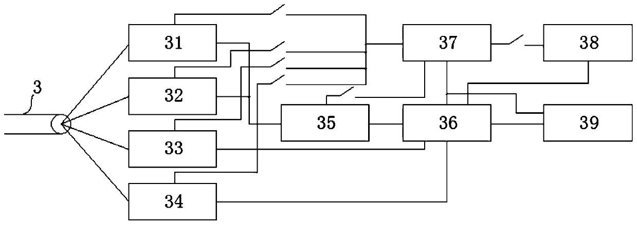
[0062] Combined with the manual Figure 1-Figure 6 , this embodiment provides a flow measurement device that can be used in a partially filled drainage pipe, which is a split structure, including a streamlined probe 1 and a flowmeter host 2, and the streamlined probe 1 and the flowmeter host 2 are connected through a waterproof cable 3 connection, where
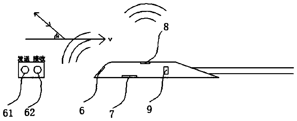
[0063] The streamlined probe 1 is a fully enclosed waterproof structure, wherein the front end of the streamlined probe 1 is provided with a first hydroacoustic transducer 61 and a second hydroacoustic transducer 62 in parallel, and a third hydroacoustic transducer is provided at the top 8. A pressure transmitter 7 is provided at the bottom and a temperature sensor 9 is provided at the rear end, wherein,
[0064] The first hydroacoustic transducer 61 and the second hydroacoustic transducer 62 are respectively coupled to the flowmeter host 2, and by using the principle of ultrasonic Doppler, the deviation of the frequency of ...
Embodiment 2
[0104] The measuring device of this embodiment adopts a split structure and includes two components: a streamlined probe 1 integrating five sensors and a flowmeter host 2, and the streamlined probe 1 and the flowmeter host 2 are connected by a special waterproof cable 3 .
[0105] The waterproof cable 3 contains a plurality of signal wires and an air guide tube 17 . The cable is provided with a desiccant hub 22 near the flowmeter host 2, and the cable air duct 17 is connected to the air duct 17 of the desiccant hub 22 through the second air chamber 19 in the waterproof plug 20, and the remaining signal wires in the cable pass through The waterproof plug 20 is connected to the waterproof interface of the host.
[0106] The desiccant center 22 is a hollow structure with a replaceable built-in desiccant, which is used to absorb the moisture in the humid air in the inspection well to ensure that the probe and the air duct 17 are dry. The desiccant center 22 has a detachable botto...
Embodiment 3
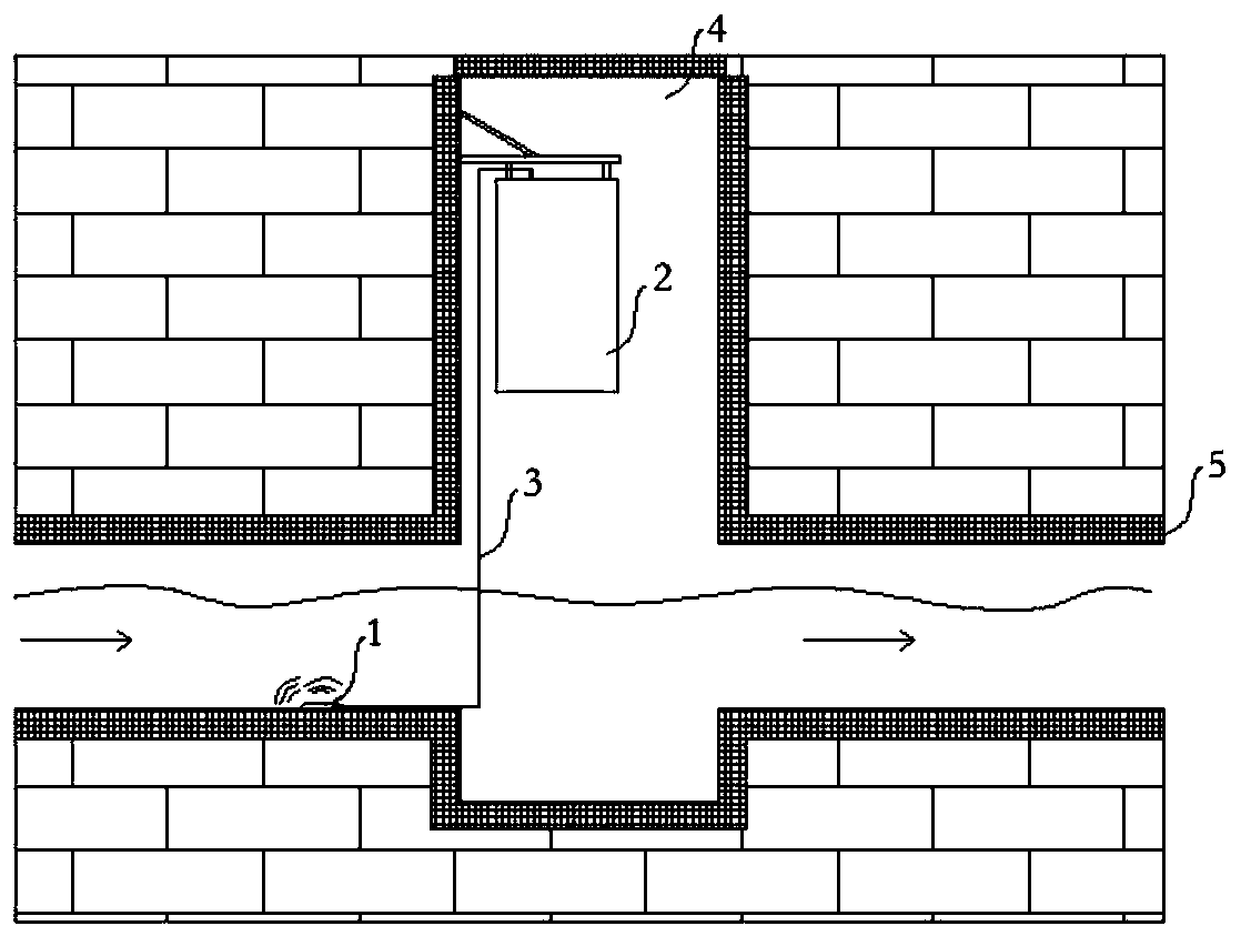
[0148] The embodiment of the present application is an application embodiment. The above-mentioned embodiment 1 can be used for the installation and configuration process of the flow measurement device of a partially filled drainage pipeline. See figure 1 .
[0149] The composition structure is that a streamlined probe 1 is fixed near the bottom of the pipeline, the flowmeter host 2 is suspended on the wall of the inspection well, and the flowmeter host 2 and the streamlined probe 1 are connected by a waterproof cable 3 .
[0150] Step S301, firstly fix the waterproof streamlined probe 1 horizontally to the position close to the bottom of the pipeline, generally select the front side to face the direction of incoming water, see figure 2 ; If there is sludge deposition at the bottom of the pipeline, the waterproof probe must be installed on the upper side of the sediment layer; the flowmeter host 2 is installed on the wall of the inspection well;
[0151] Step S302, after ins...
PUM
 Abstract
Description
Claims
Application Information
 - R&D
- Intellectual Property
- Life Sciences
- Materials
- Tech Scout
- Unparalleled Data Quality
- Higher Quality Content
- 60% Fewer Hallucinations
Browse by: Latest US Patents, China's latest patents, Technical Efficacy Thesaurus, Application Domain, Technology Topic, Popular Technical Reports.
© 2025 PatSnap. All rights reserved.Legal|Privacy policy|Modern Slavery Act Transparency Statement|Sitemap|About US| Contact US: help@patsnap.com


