Flow measuring device for partially filled pipe drainage pipeline

A technology for flow measurement devices and drainage pipes, which is applied in the directions of measurement devices, flow measurement/mass flow measurement, liquid/fluid solid measurement, etc. It can solve the problems that flow technology is difficult to apply, and achieve simplified installation and maintenance, high practical value, Accurate effect on depth and velocity measurements

Active Publication Date: 2018-07-24
TAIHUA WISDOM IND GRP CO LTD
View PDF11 Cites 14 Cited by
  • Summary
  • Abstract
  • Description
  • Claims
  • Application Information

AI Technical Summary

Problems solved by technology

[0006] The technical problem to be solved by the present invention is to provide a non-full drainage pipe flow measurement device, which can realize flow measurement under both full and partly full drainage pipe conditions, and solve the existing problems determined by the actual construction conditions of the drainage pipe. Technical problems that flow technology is difficult to apply

Method used


Image

  • Flow measuring device for partially filled pipe drainage pipeline
  • Flow measuring device for partially filled pipe drainage pipeline
  • Flow measuring device for partially filled pipe drainage pipeline

Examples


Embodiment 1

[0062] Combined with the manual Figure 1-Figure 6 , this embodiment provides a flow measurement device that can be used in a partially filled drainage pipe, which is a split structure, including a streamlined probe 1 and a flowmeter host 2, and the streamlined probe 1 and the flowmeter host 2 are connected through a waterproof cable 3 connection, where

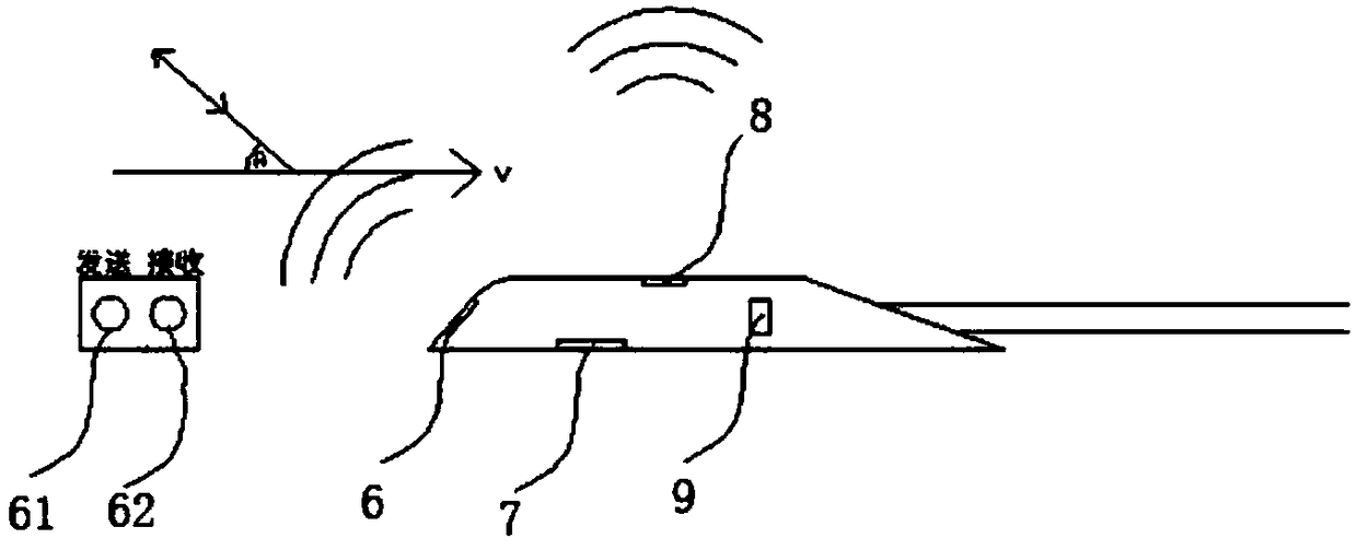
[0063] The streamlined probe 1 is a fully enclosed waterproof structure, wherein the front end of the streamlined probe 1 is provided with a first hydroacoustic transducer 61 and a second hydroacoustic transducer 62 in parallel, and a third hydroacoustic transducer is provided at the top 8. A pressure transmitter 7 is provided at the bottom and a temperature sensor 9 is provided at the rear end, wherein,

[0064] The first hydroacoustic transducer 61 and the second hydroacoustic transducer 62 are respectively coupled to the flowmeter host 2, and by using the principle of ultrasonic Doppler, the deviation of the frequency of ...

Embodiment 2

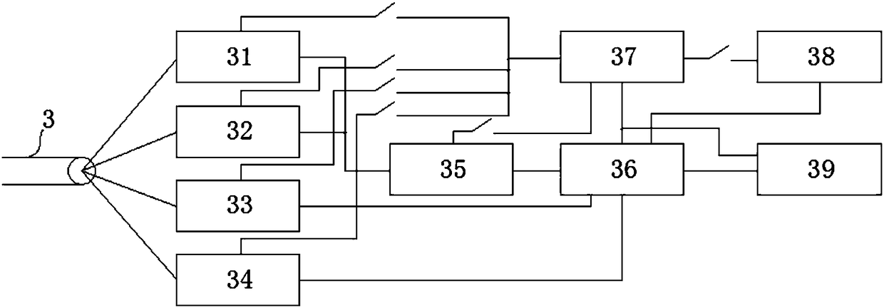
[0104] The measuring device of this embodiment adopts a split structure and includes two components: a streamlined probe 1 integrating five sensors and a flowmeter host 2, and the streamlined probe 1 and the flowmeter host 2 are connected by a special waterproof cable 3 .

[0105] The waterproof cable 3 contains a plurality of signal wires and an air guide tube 17 . The cable is provided with a desiccant hub 22 near the flowmeter host 2, and the cable air duct 17 is connected to the air duct 17 of the desiccant hub 22 through the second air chamber 19 in the waterproof plug 20, and the remaining signal wires in the cable pass through The waterproof plug 20 is connected to the waterproof interface of the host.

[0106] The desiccant center 22 is a hollow structure with a replaceable built-in desiccant, which is used to absorb the moisture in the humid air in the inspection well to ensure that the probe and the air duct 17 are dry. The desiccant center 22 has a detachable botto...

Embodiment 3

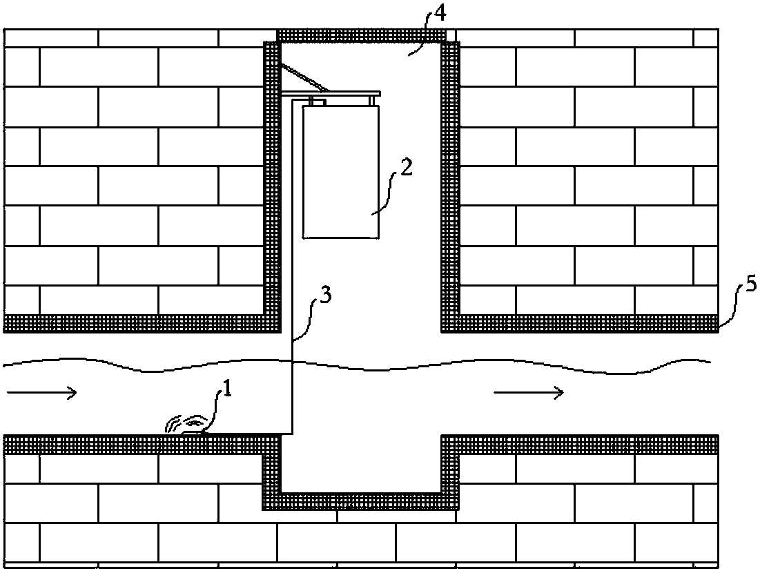
[0148] The embodiment of the present application is an application embodiment. The above-mentioned embodiment 1 can be used for the installation and configuration process of the flow measurement device of a partially filled drainage pipeline. See figure 1 .

[0149] The composition structure is that a streamlined probe 1 is fixed near the bottom of the pipeline, the flowmeter host 2 is suspended on the wall of the inspection well, and the flowmeter host 2 and the streamlined probe 1 are connected by a waterproof cable 3 .

[0150] Step S301, firstly fix the waterproof streamlined probe 1 horizontally to the position close to the bottom of the pipeline, generally select the front side to face the direction of incoming water, see figure 2 ; If there is sludge deposition at the bottom of the pipeline, the waterproof probe must be installed on the upper side of the sediment layer; the flowmeter host 2 is installed on the wall of the inspection well;

[0151] Step S302, after ins...


PUM


Abstract

The invention discloses a flow measuring device for a partially filled pipe drainage pipeline. The measuring device is a separated type structure, the device comprises a streamline probe and a flowmeter host, and the streamline probe is connected with the flowmwter host through a waterproof cable; the streamline probe is a totally-enclosed waterproof structure, wherein the front end of the streamline probe is provided with a first underwater acoustic transducer and a second underwater acoustic transducer in parallel, the top end is provided with a third underwater acoustic transducer, the bottom of the probe is provided with a pressure transmitter, and the back end is provided with a temperature sensor; the flowmeter host comprises an ultrasonic Doppler flow rate measuring module, ultrasonic liquid level measuring module, a pressure transmitter measuring module, a temperature measuring module, an FPGA operational module, an MCU main control module, a battery and voltage-stabilized source module, a GPRS communication module and a debugging interface circuit. According to the device, through the separated type structure of integrating the streamline probe with five sensors and the host, the problems are simplified that the flowmeter installation and maintenance are difficult.

Description

technical field [0001] The invention relates to the field of ultrasonic Doppler flow measurement, in particular to a flow measurement device for measuring partially filled drainage pipes. Background technique [0002] In recent years, with the introduction of the concept of sponge city, more and more cities have carried out the construction of sponge city, and the construction of sponge city first needs to be based on the analysis of urban drainage data, so that the monitoring of urban drainage pipeline flow Demand came into being. The flow measurement of drainage pipes (referring to pipes that collect and discharge sewage, waste water, and rainwater) has always been a difficult problem in the field of flow measurement, because drainage pipes are gravity flow pipes, that is, in the absence of pressure, relying on the slope of the drainage pipe to rely on itself It flows downward due to the action of gravity, which is the most commonly used method in rainwater and sewage dis...

Claims


Application Information

Patent Timeline
Patent Type & Authority Applications(China)
IPC IPC(8): G01F1/66
CPCG01F1/663
Inventor 赵吉祥马述杰
Owner TAIHUA WISDOM IND GRP CO LTD
Why Eureka
Try Eureka