Optical projection module and control method thereof

A technology of optical projection and control method, applied in optics, optical components, instruments, etc., can solve the problems of human eye damage, inability to effectively diffract laser light, and laser energy becoming stronger, etc., to achieve the effect of avoiding damage

Active Publication Date: 2018-07-24
KUNSHAN Q TECH CO LTD
View PDF12 Cites 4 Cited by
  • Summary
  • Abstract
  • Description
  • Claims
  • Application Information

AI Technical Summary

Problems solved by technology

[0003] The structured light pattern projected by the optical projection module is generally obtained by receiving the laser light emitted by a laser (such as VCSEL) through a collimator lens, converging it to form a parallel beam and projecting it outward, and then through a diffractive optical device (DOE). The parallel beam projected by the col

Method used


Image

  • Optical projection module and control method thereof
  • Optical projection module and control method thereof
  • Optical projection module and control method thereof

Examples


Example Embodiment

[0024] In order to further explain the technical means and effects of the present invention to achieve the intended purpose of the invention, the specific implementation, structure, features and effects of the present invention will be described in detail below in conjunction with the accompanying drawings and examples.

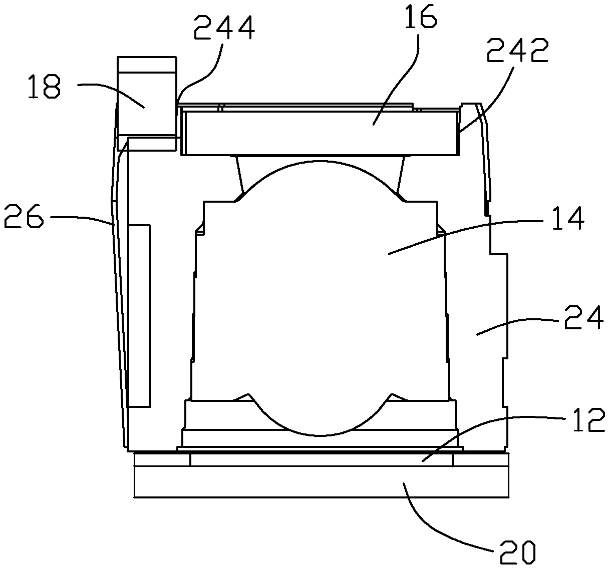
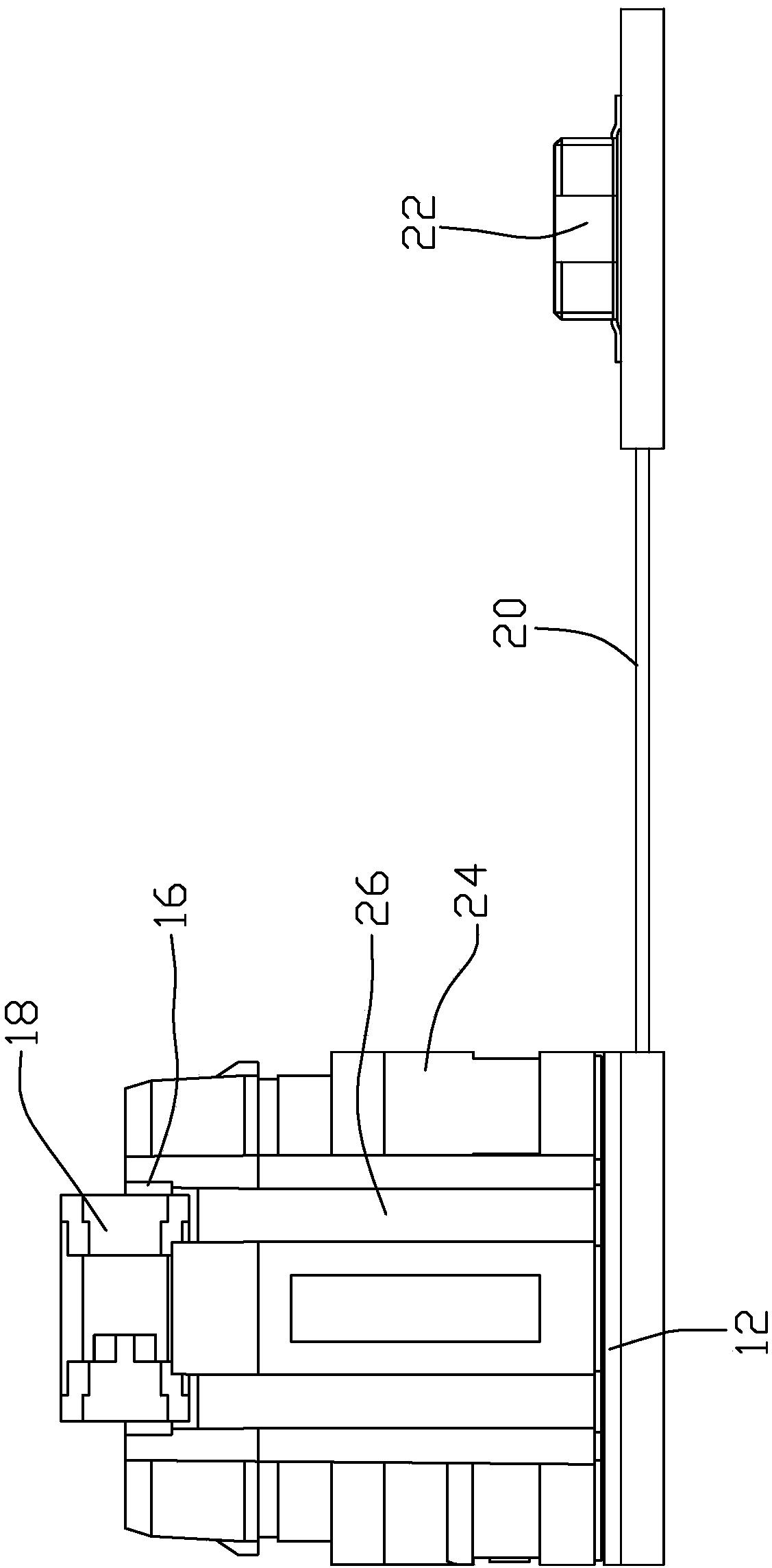
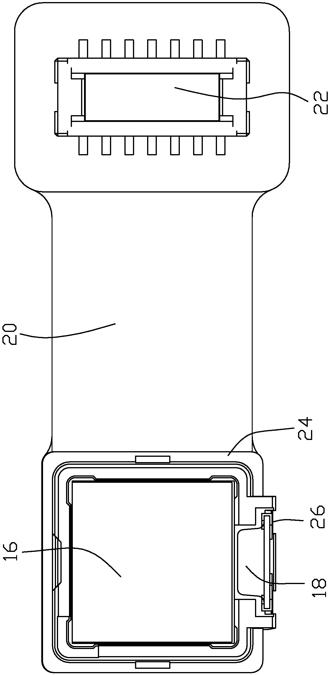
[0025] like Figure 1 to Figure 4 As shown, an embodiment of the present invention provides an optical projection module, including a laser emitting device 12 , a collimating lens 14 , a diffraction device 16 , a photosensitive device 18 , a circuit board 20 and a connector 22 . The collimating lens 14 is arranged above the laser emitting device 12 , the diffractive device 16 is arranged above the collimating lens 14 , and the photosensitive device 18 is arranged on the side of the diffractive device 16 to sense the light emitted by the diffractive device 16 to the side circumference. The circuit board 20 is electrically connected to the laser emitting device...


PUM


Abstract

The invention discloses an optical projection module and a control method thereof. The optical projection module comprises a laser emission device, a collimating lens, a diffraction apparatus and an optical sensing device, wherein the collimating lens is arranged above the laser emission device; the diffraction apparatus is arranged above the collimating lens; and the optical sensing device is arranged on a side face of the diffraction apparatus and is used for sensing light rays emitting towards side periphery by the diffraction apparatus. The control method comprises the following steps: turning on the laser emission device; sensing light rays emitted from the diffraction apparatus by utilizing the optical sensing device, and generating different electric induction signals according to intensity of the light rays; judging whether operation of the diffraction apparatus is normal according to changes of the electric induction signals transmitted by the optical sensing device, and controlling the laser emission device to be turned off when the operation of the diffraction apparatus is judged to be abnormal. According to the optical projection module and the control method thereof, different electric induction signals are transmitted by sensing the light rays at the side periphery of the diffraction apparatus by the optical sensing device, whether the operation of the diffractionapparatus is normal is judged, the laser emission device is turned off when the operation is abnormal, and the condition that human eyes are damaged due to strong light emitting from the diffractionapparatus is avoided.

Description

technical field [0001] The invention relates to the technical field of electronic products, in particular to an optical projection module and a control method thereof. Background technique [0002] At present, structured light technology has gradually developed into a relatively mature stereoscopic imaging technology, which can be applied to face recognition, human-computer interaction, three-dimensional space scanning and other fields. The basic working principle of structured light technology is that the projection of optical projection modules has a certain Structured light patterns, such as scattered random scattering spots, project these random scattering spots on the surface of the object, and then collect the scattering spots projected on the surface of the object through the image acquisition device, and then calculate the depth of the object Information, realize face recognition, human-computer interaction, three-dimensional space scanning and other functions. [0...

Claims


Application Information

Patent Timeline
IPC IPC(8): G02B27/42
CPCG02B27/4233
Inventor 许杨柳金元斌邓爱国徐爱新胡远鹏
Owner KUNSHAN Q TECH CO LTD
Why Eureka
Try Eureka