
LCD module making method

A production method and module technology, applied in chemical instruments and methods, optics, instruments, etc., can solve the problems of slow production process, polarizers and glass panels are easy to absorb foreign matter, etc., to improve production speed, simple production method, avoid The effect of the sputtering phenomenon

Inactive Publication Date: 2018-07-24
SHENZHEN ZHONGSHEN OPTOELECTRONICS
View PDF5 Cites 0 Cited by
  • Summary
  • Abstract
  • Description
  • Claims
  • Application Information

AI Technical Summary

Problems solved by technology

[0004] The main purpose of the present invention is to propose a method for manufacturing an LCD module to solve the problem existing in the prior art that the manufactu

Method used


Image

  • LCD module making method
  • LCD module making method
  • LCD module making method

Examples


Example Embodiment

[0024] It should be understood that the specific embodiments described herein are only used to explain the present invention, but not to limit the present invention.

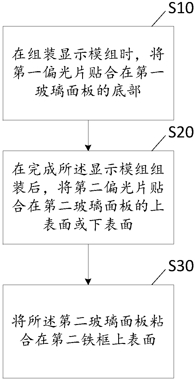
[0025] reference figure 1 , figure 1 It is a schematic diagram of the process in the first embodiment of the present invention.

[0026] Such as figure 1 As shown, an LCD module manufacturing method of the present invention includes the following steps:

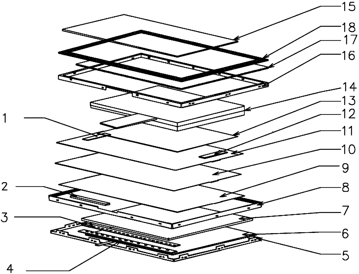
[0027] Step S10, when assembling the display module, the first polarizer 13 is attached to the bottom of the first glass panel 14 (such as image 3 Shown);

[0028] The LCD module manufacturing method of the present invention is aimed at medium and large electronic products, that is, the surface area of ​​the display screen or the second glass panel of the LCD module is greater than 600 square centimeters; in step S10, when the display module is assembled, Such as image 3 As shown, the display module includes a first glass panel 14, a first polarizer 13, a light guide...


PUM


Abstract

The invention discloses an LCD module making method. The method comprises the following steps that S10, when a display module is assembled, a first polaroid fits the bottom of a first glass panel; S20, after display module assembling is completed, a second polaroid fits the upper surface or the lower surface of a second glass panel; S30, the second glass panel adheres to the upper surface of a second iron frame. Accordingly, the problems that in the prior art, in the making process, due to the fact that fine control is needed, the making process is low, and foreign matter is likely to be adsorbed between the polaroids and the glass panels are solved, and the display effect is improved.

Description

technical field [0001] The invention belongs to the technical field of LCD modules, and in particular relates to a method for manufacturing an LCD module. Background technique [0002] At present, the LCD module (display driver module) is an important part of electronic products, which greatly affects the display effect of electronic products; among them, in the existing module production methods, most of them are glass panel components and LCM modules The lamination is completed, and the lamination process adopted is full lamination or frame lamination. However, the existing lamination process generally requires bonding polarizers on both the top and bottom surfaces of the glass panel in the LCM module, so as to realize the display and imaging of electronic products. In the production process, it is necessary to bond two polarizers on the top and bottom surfaces of the glass panel respectively. This double-sided bonding method is suitable for LCD modules of medium and larg...

Claims


Application Information

Patent Timeline
IPC IPC(8): G02F1/1333
CPCG02F1/1333G02F1/133308G02F1/133325G02F1/133331B32B7/12B32B17/06B32B17/066G02F2201/50G02F2201/508G02F2202/28
Inventor 姚莉莉王亚锋林勤华
Owner SHENZHEN ZHONGSHEN OPTOELECTRONICS
Learn More