
Automatic tool machine for detaching and mounting motor

A tooling and automatic technology, applied in the direction of electric components, manufacturing motor generators, electrical components, etc., can solve the problems of cutting or grinding, unstable and damaged wire drawing force lines, and achieve the effect of improving efficiency

Pending Publication Date: 2018-07-24
广东卓晟智能装备有限公司
View PDF10 Cites 0 Cited by
  • Summary
  • Abstract
  • Description
  • Claims
  • Application Information

AI Technical Summary

Problems solved by technology

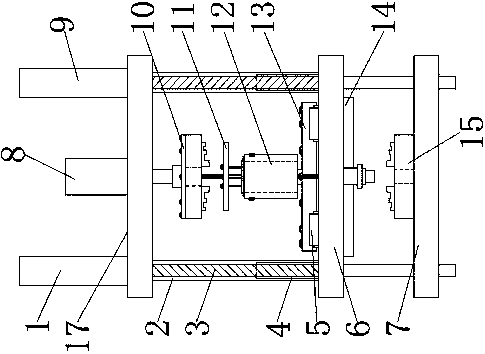
[0005] The object of the present invention is to provide an automatic tooling machine for disassembling and assembling motors, to solve the problem that the disassembling and assembling of existing spindle motors proposed in the above-mentioned background technology is mainly completed by a puller. For some precision assembled spindle motors, because there is no The space conditions used by the puller require cutting or grinding to disassemble the bearing; when disassembling a win-fit bearing, the pull force of the general puller cannot complete the disassembly; usually only wire drawing can be used when disassembling coaxial parts such as balance discs and code discs , the force line is unstable during wire drawing and disassembly, and it is easy to cause damage due to deviation; installation usually adopts the method of sleeve and hammer, manual knocking installation, easy to damage bearings, code discs, balance discs, etc., so the existing transmission tools cannot Efficient and reliable disassembly and assembly of the spindle motor

Method used


Image

  • Automatic tool machine for detaching and mounting motor
  • Automatic tool machine for detaching and mounting motor
  • Automatic tool machine for detaching and mounting motor

Examples


Embodiment Construction

[0018] The following will clearly and completely describe the technical solutions in the embodiments of the present invention with reference to the accompanying drawings in the embodiments of the present invention. Obviously, the described embodiments are only some, not all, embodiments of the present invention. Based on the embodiments of the present invention, all other embodiments obtained by persons of ordinary skill in the art without making creative efforts belong to the protection scope of the present invention.

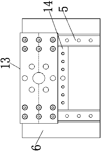
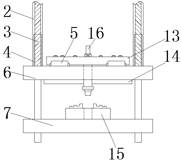
[0019] see Figure 1-4 , the present invention provides a technical solution: an automatic tooling machine for disassembling and assembling motors, including a workbench 6, a movable guide rail 5 is welded and connected to the top of the workbench 6, and a movable fixed rod 14 is fixedly connected to the bottom of the workbench 6, and the workbench 6. The movable structure is formed by the hydraulic movable rod 2 and the sliding fixed rod 3, and the workbench ...


PUM


Abstract

The invention relates to an automatic tool machine for detaching and mounting a motor. The automatic tool machine comprises a workbench, wherein movable guide rails are connected to the upper side ofthe workbench in an inlaying manner; a movable fixing rod is fixedly connected to the bottom of the workbench; sliding fixing rods are connected to the two ends of the movable guide rails; hydraulic movable rods are fixedly connected to the front sides of the sliding fixing rods; a top plate is arranged at the top end of a first four-corner chuck; a main oil cylinder is mounted at the top end of the top plate; a second four-corner chuck is connected to the lower side of the movable fixing rod; a bottom plate is fixedly connected to the bottom of the second four-corner chuck. The automatic toolmachine for detaching and mounting the motor can automatically fix a spindle motor through a workpiece grabbing plate, a tool supporting platform and the movable fixing rod and then upwardly drive the first four-corner chuck and the workpiece grabbing plate through the main oil cylinder, so that the workpiece grabbing plate can detach a workpiece inside the spindle motor, and the problems that the conventional spindle motor detaching and mounting working efficiency is not high and parts are easily damaged are solved.

Description

technical field [0001] The invention relates to the technical field of disassembling and assembling a spindle motor, in particular to an automatic tooling machine for disassembling and assembling a motor. Background technique [0002] Spindle motor, also called high-speed motor, refers to an AC motor with a rotation speed exceeding 10,000 rpm. It is mainly used in wood, aluminum, stone, hardware, glass, PVC and other industries. It has the advantages of fast speed, small size, light weight, low material consumption, low noise, low vibration, etc., and is more and more valued and applied by related industries. . [0003] In a modern society with rapid technological progress, due to the wide application of spindle motors, coupled with its meticulous workmanship, fast speed and high processing quality, other ordinary motors cannot meet the technical requirements of spindle motors and play a role in industrial production. It plays an important role, so the spindle motor is par...

Claims


Application Information

Patent Timeline
Patent Type & Authority Applications(China)
IPC IPC(8): H02K15/00H02K15/16
CPCH02K15/0006H02K15/16
Inventor 朱国顺
Owner 广东卓晟智能装备有限公司
Learn More