Vacuum cleaner utilizing cyclone tube for separation

A technology of vacuum cleaners and cyclone tubes, applied in vacuum cleaners, suction filters, applications, etc., can solve the problems of high maintenance costs, inconvenient use of manpower and material resources, and low separation efficiency of vacuum cleaners, so as to facilitate replacement, improve cleanliness, and reduce complexity Effect

Inactive Publication Date: 2018-07-27
航宇智创科技(北京)有限公司
View PDF6 Cites 3 Cited by
  • Summary
  • Abstract
  • Description
  • Claims
  • Application Information

AI Technical Summary

Problems solved by technology

[0005] Aiming at the problems in the prior art that the separation efficiency of the vacuum cleaner is low, the maintenance cost is high, and it takes a lot of manpower and material resources to make it inconvenient for people to use, the purpose of the present invention is to provide a vacuum cleaner that uses a cyclone tube for separation. The tube has a vane structure, which makes the passing air rotate at a high speed, giving the solid pollutants in the air a radial velocity and a tangential velocity. During the high-speed rotation, the solid pollutants are thrown to the tube wall due to the inertial centrifugal force , and finally discharged through the dust outlet of the cyclone tube, which greatly improves the separation efficiency

Method used


Image

  • Vacuum cleaner utilizing cyclone tube for separation
  • Vacuum cleaner utilizing cyclone tube for separation
  • Vacuum cleaner utilizing cyclone tube for separation

Examples


Embodiment Construction

[0022] The present invention will be further described below in conjunction with the accompanying drawings and specific embodiments, but not as a limitation of the present invention.

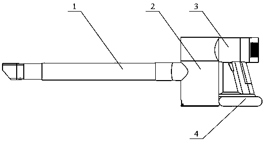
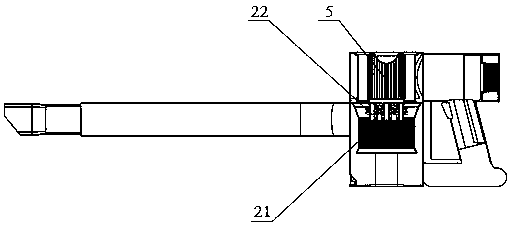
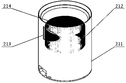
[0023] Please see Figure 1 to Figure 9 , a vacuum cleaner utilizing a cyclone tube for separation, comprising a dust collection mechanism 1, a separation mechanism 2, a dust suction fan 3 and a power supply mechanism 4, the dust collection mechanism 1, the separation mechanism 2, and the dust suction fan 3 are connected in sequence, and the The power supply mechanism 4 is connected to the dust extraction fan 3 and the separation mechanism 2, wherein the separation mechanism 2 includes a first separation mechanism 21 and a second separation mechanism 22, and the first separation mechanism 21 includes a first dust storage tank 211 And the first separation device 212, the first dust tank 211 is provided with an air inlet 213 along the tangential direction, the dust suction mechanism 1 communicates...


PUM


Abstract

The invention discloses a vacuum cleaner utilizing a cyclone tube for separation. The cyclone tube in the vacuum cleaner has a blade structure, so that bypassing air is enabled to rotate at a high speed to give a radial speed and a tangential speed to solid pollutants in the air; the solid pollutants are discharged through a dust discharging port of the cyclone tube under action of inertial centrifugal force, so that separation efficiency is improved greatly.

Description

technical field [0001] The invention relates to a cleaning and dust removal device, in particular to a vacuum cleaner using a cyclone tube for separation. Background technique [0002] With the development of the economy and the improvement of people's living standards, people have higher and higher requirements for the living environment such as offices, cars and family residences. In order to remove pollutants such as hair in the aforementioned spaces, a convenient and practical vacuum cleaner for cleaning became people's first choice. [0003] At present, there are also various vacuum cleaners on the market. The vacuum cleaners currently on sale usually use cyclone separation technology and filter element interception to remove dust: in this case, the airflow entering the vacuum cleaner is often pre-separated by the cyclone separation device. , to remove the large particles in the airflow, and the remaining small particles are still intercepted by traditional filter mate...

Claims


Application Information

Patent Timeline
Patent Type & Authority Applications(China)
IPC IPC(8): A47L5/22A47L9/16
CPCA47L5/22A47L9/1691
Inventor 魏来姜新生郭鹏
Owner 航宇智创科技(北京)有限公司
Why Eureka
Try Eureka