Supercharge Your Innovation With Domain-Expert AI Agents!

Spiral conveying device

A spiral conveying device, spiral technology, applied in the direction of conveyor objects, transportation and packaging, rollers, etc., can solve problems such as low efficiency, excessive product speed, and large product wear

Pending Publication Date: 2018-07-27
上海苏腾机械设备有限公司
View PDF0 Cites 0 Cited by
  • Summary
  • Abstract
  • Description
  • Claims
  • Application Information

AI Technical Summary

Problems solved by technology

[0003] The disadvantage of the first type of device is its limitation. Due to the large resistance of the fixed roller (cannot rotate), it is only suitable for cartons or packaged items.
The disadvantage of the second device is that it is limited and not durable. Since the rollers are installed in the shape of an O-belt ∞, one roller rotates forward to drive the other roller to reverse. , suitable for cartons or packaged items
The disadvantage of the third device is high cost and low efficiency
When the conveying volume is large, the accumulation cannot be prevented, because the cylinder cannot be separated and disengaged during accumulation
[0004] Considering factors such as the floor area of ​​the equipment, the size of the product, and the cost of the equipment, the designed equipment is often not ideal. The actual situation is that the product that slides down is too fast, resulting in stalling and collision damage.

Method used


Image

  • Spiral conveying device

Examples


Embodiment 1

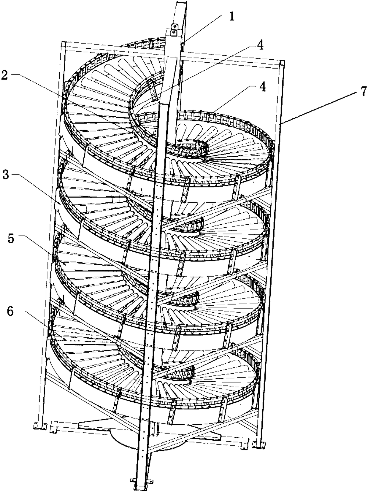
[0024] A kind of screw conveying device, its structure is as figure 1 As shown, it includes a support and a four-layer spiral conveying channel fixedly installed on the support. The conveying channel is provided with evenly distributed rollers. The rollers include free rollers 5 and damping rollers 6 that are evenly and spaced in the free rollers 5. There are two magnetic damping rollers 6 on one layer of conveying channel, and the two magnetic damping rollers are respectively arranged in the middle and tail of each layer of conveying channel. Exit to leave. By setting the damping roller 6 in the free roller 5, when the workpiece passes above the free roller 5, due to the gravity of the workpiece itself, it will accelerate and slide forward under the action of the free roller 5, so the speed of the workpiece gradually increases; When passing above the damping roller 6, since the damping roller 6 has greater resistance when rolling, it will hinder the advancement of the workpi...


PUM


Abstract

The invention relates to a spiral conveying device. The spiral conveying device comprises a support and multiple layers of spiral conveying channels fixedly arranged on the support. The conveying channels are provided with evenly-distributed rollers. The rollers include the free rollers and the damping rollers evenly arranged in the free rollers at intervals. Each layer of conveying channel is provided with two to four damping rollers. To-be-conveyed workpieces enter from a top end inlet of the conveying channels and get out of a bottom end outlet of the conveying channels. Compared with the prior art, the damping rollers are arranged in the free rollers so that the descending speed of the workpieces cannot be too high, and it is guaranteed that the workpieces cannot be damaged due to collisions; and commercially-available magnetic damping rollers or inner friction plate damping rollers are adopted as the damping rollers, cost is low, power drive is not needed, the spiral conveying device can be used in any place, and the spiral conveying device is simple and convenient to use.

Description

technical field [0001] The invention relates to the technical field of automobile production lines, in particular to a screw conveying device. Background technique [0002] Automobile production lines often transport workpieces such as tires from upstairs to downstairs for assembly, packaging, etc. In the case of meeting production capacity and technical requirements, reliable and low-cost unpowered screws are basically used to replace elevators. There are currently three types of reduction gears for screw conveyor systems on the market. The first is to add 1-2 fixed rollers to each layer. The second is to add 4-8 rollers with O-shaped grooves on each layer, and install them in the shape of O-shaped ∞ to play the role of forward and reverse. The third is to increase 2 cylinder jacking blocks on each floor. [0003] The disadvantage of the first device is limitation, because the resistance of the fixed roller (cannot rotate) is large and the product is worn and worn, only ...

Claims


Application Information

Patent Timeline
Patent Type & Authority Applications(China)
IPC IPC(8): B65G13/08B65G39/02B65G13/04
CPCB65G13/04B65G13/08B65G39/02
Inventor 罗俊
Owner 上海苏腾机械设备有限公司
Features
  • R&D
  • Intellectual Property
  • Life Sciences
  • Materials
  • Tech Scout
  • Unparalleled Data Quality
  • Higher Quality Content
  • 60% Fewer Hallucinations
Learn More