
High-cover capping machine

A high-cap capping machine and rack technology, which is used in the directions of capping containers tightly with caps, capping machine safety/control, flanged caps, etc. Meet the requirements and other issues to achieve the effect of cleaning the production process, reducing the probability of dust entering the interior of the tank, and reducing the probability of failure

Active Publication Date: 2018-07-27
上海达和荣艺包装机械有限公司
View PDF11 Cites 7 Cited by
  • Summary
  • Abstract
  • Description
  • Claims
  • Application Information

AI Technical Summary

Problems solved by technology

[0004] This high-cap automatic capping machine conveys the cap and presses the cap on the tank body by setting the cap pressing mechanism and the cap conveying mechanism, so as to realize the fixation between the cap and the tank body, but this high-cap The automatic capping machine can only press the lid on the tank body. When the icon on the lid and the tank body need to cooperate with each other, the high-cap automatic capping machine directly presses the tank body and the lid, so that the lid and the can The fit of the body does not meet the requirements, so that the high-cap automatic capping machine is only suitable for a specific tank body, resulting in a smaller scope of application

Method used


Image

  • High-cover capping machine
  • High-cover capping machine
  • High-cover capping machine

Examples


Embodiment Construction

[0043] The present invention will be further described with reference to the accompanying drawings.

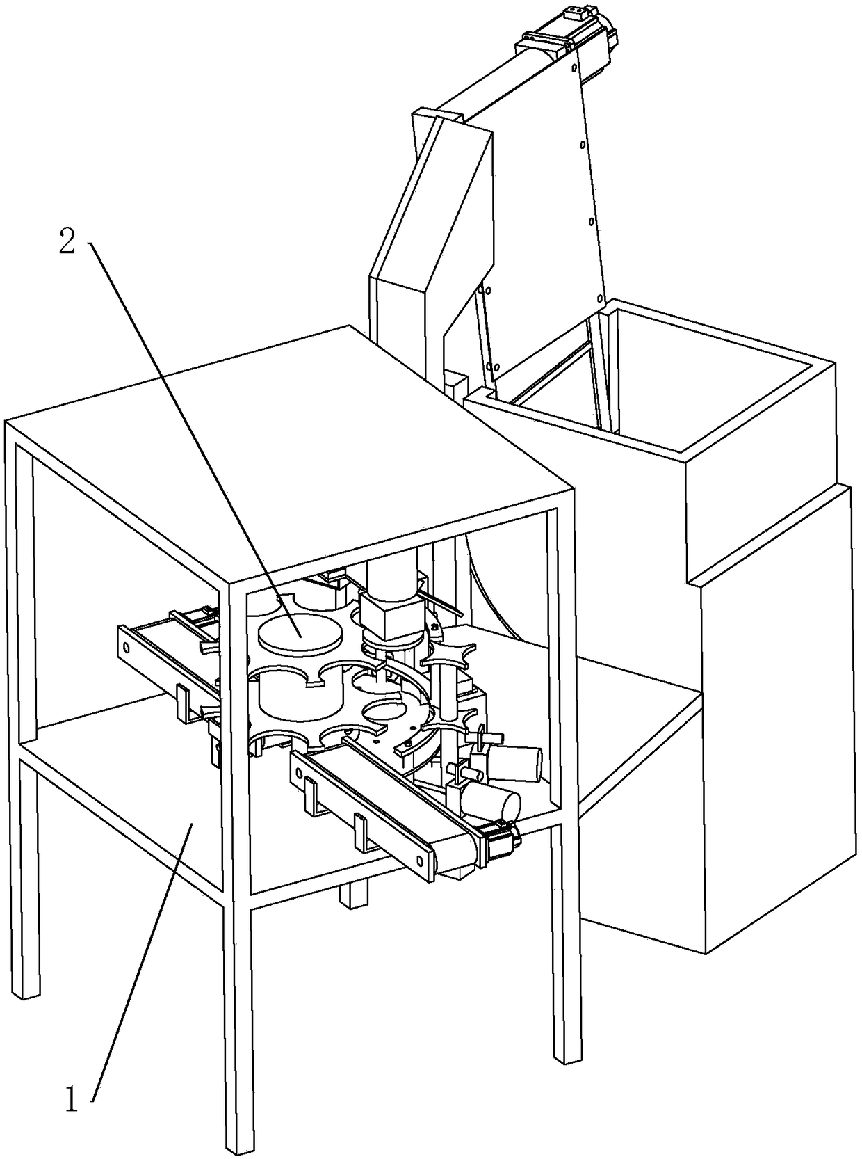
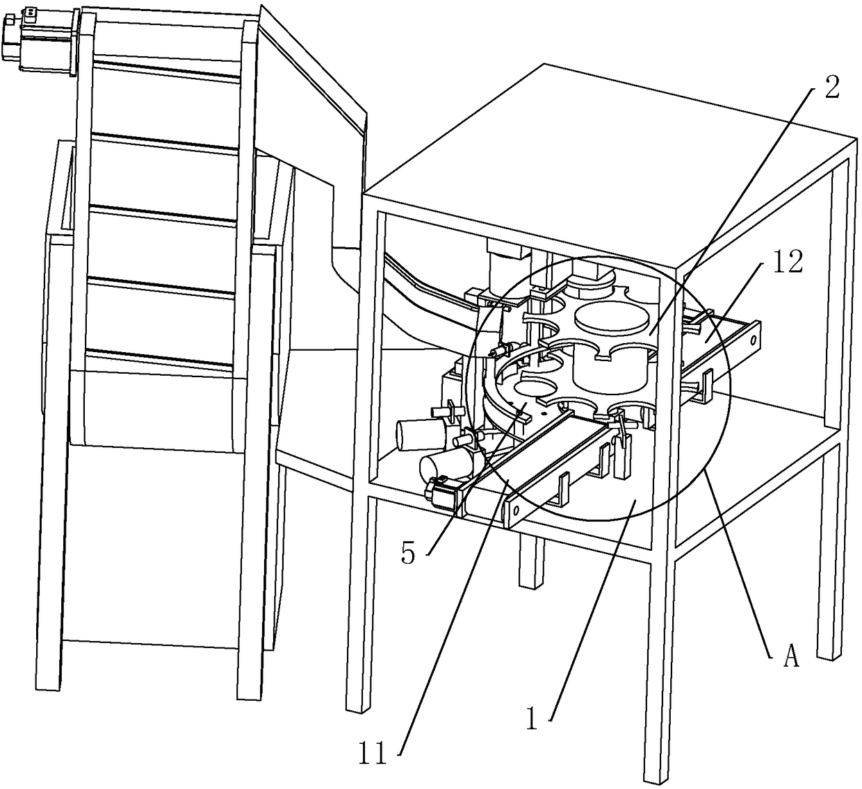
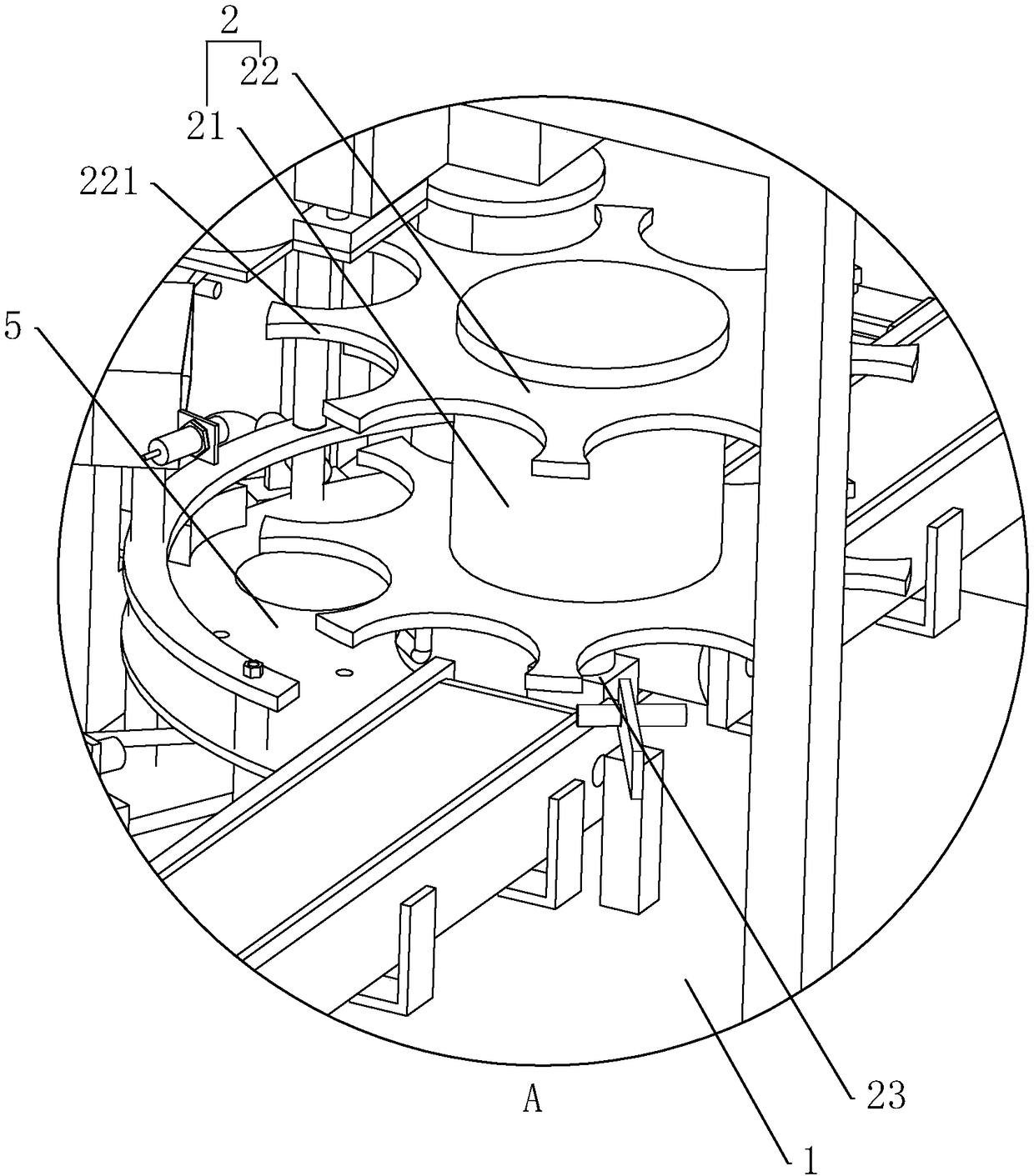
[0044] Such as figure 1 As shown, a high-cap capping machine includes a frame 1 on which a conveying carousel 2 is rotatably connected. Such as figure 2 and image 3 As shown, the conveying carousel 2 is driven to rotate by a rotating motor 23 , and the rotating motor 23 is fixedly connected to the frame 1 . The conveying carousel 2 includes a cylindrical fixed part 21 fixedly connected to the output shaft of the rotating motor 23, and a conveying disc body 22 fixedly connected to both ends of the fixing part 21. Shaped delivery grooves 221, the delivery grooves 221 are evenly distributed along the axis of the delivery tray body 22. A feed conveyor 11 and a discharge conveyor 12 are installed on the frame 1 , and the feed conveyor 11 and the discharge conveyor 12 are located on both sides of the conveying turntable 2 . The frame 1 is fixedly connected with a fan-shaped r...


PUM


Abstract

The invention relates to the field of capping devices, and discloses a high-cover capping machine. The machine comprises a machine frame, the machine frame is rotationally connected with a conveying rotating disc, the conveying rotating disc is driven by a rotating motor to rotate, a conveying groove is formed in the peripheral side of the conveying rotating disc, the machine frame is provided with a feeding conveyor and a discharging conveyor which are located on the two sides of the conveying rotating disc, a first adjusting assembly is arranged on the machine frame, the first adjusting assembly comprises a vacuum suction cup and a first control assembly which are arranged on the machine frame, a second adjusting assembly is arranged on the machine frame, the second adjusting assembly comprises an adjusting disc and a second control assembly which are arranged on the machine frame, a pressing assembly is arranged on the machine frame, and the pressing assembly is close to the discharging conveyer. The machine has the following advantages and effects that according to the scheme, the novel mechanical structure is utilized, the positions of a tank body and a cover can be adjusted by arranging the first adjusting assembly, the second adjusting assembly and the pressing assembly, the cover and the tank body in different covering modes can be matched, so that the adaptive range ofthe high-cover capping machine is relatively wide.

Description

technical field [0001] The invention relates to a capping device, more specifically, it relates to a high cap capping machine. Background technique [0002] A capping machine is a machine that caps containers. [0003] At present, the Chinese patent with the notification number CN204400577U discloses a high cap automatic capping machine, which includes a capping mechanism, a connecting angle iron and a product conveying mechanism, and the capping mechanism and the product conveying mechanism are fixed together through the connecting angle iron , the capping mechanism includes a lower support body, a capping conveyor, a capping force mechanism and an upper support body, the lower support body is connected with the upper support body, and the capping conveyor is connected with the upper support body through the capping force mechanism . [0004] This high-cap automatic capping machine conveys the cap and presses the cap on the tank body by setting the cap pressing mechanism ...

Claims


Application Information

Patent Timeline
Patent Type & Authority Applications(China)
IPC IPC(8): B67B3/12B67B3/26B67B3/28
CPCB67B3/12B67B3/262B67B3/28
Inventor 刘元群
Owner 上海达和荣艺包装机械有限公司
Learn More