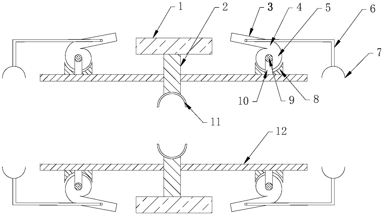
Gas discharging joint device for CNG gas filling station

A technology for gas joints and gas filling stations, which is applied to mechanical equipment, couplings, etc., can solve the problems of poor sealing performance of pipeline joints, complicated structure of pipeline joints, and reduced gas discharge efficiency, so as to achieve simple structure and avoid waste of resources. , Improve the effect of unloading efficiency

Pending Publication Date: 2018-07-27
TIANJIN LIANGHUA NEW ENERGY TECH
View PDF0 Cites 1 Cited by
  • Summary
  • Abstract
  • Description
  • Claims
  • Application Information

AI Technical Summary

Problems solved by technology

[0002] The currently used CNG gas filling station supplies gas to the gas filling station through the CNG mobile gas supply vehicle. The compressed natural gas in the mobile gas supply vehicle cannot be unloaded directly to the gas filling station. After pressure, it is unloaded into the gas storage of the gas filling station, so an unloading device is required. However, the pipe joint structure of the existing unloading device is complicated, and it takes a long time to connect with the unloading pipeline, which reduces the unloading efficiency. Moreover, the pipe joints of the existing gas unloading device are not well sealed, and there is a phenomenon of air leakage, which not only pollutes the environment, but also causes a waste of resources.

Method used


Image

  • Gas discharging joint device for CNG gas filling station

Examples


Embodiment Construction

[0017] It should be noted that, in the case of no conflict, the embodiments of the present invention and the features in the embodiments can be combined with each other.

[0018] In describing the present invention, it should be understood that the terms "center", "longitudinal", "transverse", "upper", "lower", "front", "rear", "left", "right", The orientations or positional relationships indicated by "vertical", "horizontal", "top", "bottom", "inner", "outer", etc. are based on the orientation or positional relationships shown in the drawings, and are only for the convenience of describing the present invention Creation and simplification of description, rather than indicating or implying that the device or element referred to must have a specific orientation, be constructed and operate in a specific orientation, and therefore should not be construed as limiting the invention. In addition, the terms "first", "second", etc. are used for descriptive purposes only, and should no...


PUM


Abstract

The invention provides a gas discharging joint device for a CNG gas filling station. The gas discharging joint device comprises a butt-joint sleeve, a clamping part and a sealing part. The clamping part comprises a U-shaped base, connecting pieces, movable pin shafts, a handle, a clamping rod and a clamping piece. The U-shaped base is fixedly arranged at one end of the butt-joint sleeve. The connecting pieces are symmetrically fixed to the U-shaped base. The top end of each connecting piece is provided with a mounting-inserting hole for mounting and inserting of the corresponding movable pin shaft. The handle and the base are rotationally connected through the movable pin shafts. The clamping rod is of an L-shaped structure. One end of the clamping rod is hinged to the hand-hold part of the handle through movable pins. The clamping piece is welded to the other end of the clamping rod. The sealing part comprises a rotating handle, a threaded rod and a sealing plate. The threaded rod penetrates through a threaded hole in the butt-joint sleeve. One end of the threaded rod is connected with the rotating handle. The other end of the threaded rod is connected with the sealing plate. According to the gas discharging joint device for the CNG gas filling station, the problems that the sealing property of an existing gas discharging joint device is not good, the butt-joint consumed timeis long, and operation is cumbersome are solved.

Description

technical field [0001] The invention belongs to the technical field of CNG filling equipment manufacturing, and in particular relates to a gas unloading joint device used in a CNG filling station. Background technique [0002] The currently used CNG gas filling station supplies gas to the gas filling station through the CNG mobile gas supply vehicle. The compressed natural gas in the mobile gas supply vehicle cannot be unloaded directly to the gas filling station. After pressure, it is unloaded into the gas storage of the gas filling station, so an unloading device is required. However, the pipe joint structure of the existing unloading device is complicated, and it takes a long time to connect with the unloading pipeline, which reduces the unloading efficiency. Moreover, the pipe joints of the existing air unloading device have poor sealability and air leakage, which not only pollutes the environment, but also causes waste of resources. Contents of the invention [0003]...

Claims


Application Information

Patent Timeline
IPC IPC(8): F16L37/05F16L37/20
CPCF16L37/05F16L37/20
Inventor 史志强
Owner TIANJIN LIANGHUA NEW ENERGY TECH
Why Eureka
Try Eureka