gas cooker

A gas cooker and burner technology, which is applied in the direction of burner, combustion type, combustion method, etc., can solve the problems such as the limitation of the length of the injection tube and the mixing chamber, the inability to improve the injection coefficient, and the complicated manufacturing and installation process, etc., to achieve The effect of good mixing effect, good hygienic performance and good burning effect

Active Publication Date: 2019-05-14
SHENGZHOU FUHUA GAS APPLIANCE
View PDF5 Cites 0 Cited by
  • Summary
  • Abstract
  • Description
  • Claims
  • Application Information

AI Technical Summary

Problems solved by technology

In order to improve the ejection coefficient, the ejectors currently on the market usually set the ejector long outside the base, or set the ejector inside the base, and set an arc-shaped mixing chamber at the end of the ejector tube to eject The tube and the mixing chamber are extended along the edge of the base. Due to the limitation of the volume of the base, the length of the injection tube and the mixing chamber are limited, and the purpose of improving the injection coefficient cannot be achieved.
[0004] When the existing burner is in use, the soup is easy to overflow and spills inside the burner, which causes great inconvenience to cleaning. If it is not cleaned for a long time, it is easy to breed bacteria and has poor hygienic performance.
[0005] At present, the burners on the market are generally installed on the base or inside the base after the ejector is manufactured separately. In addition to the complicated manufacturing and installation process, the overall sealing is not high enough, which has a great impact on the final combustion power.

Method used


Image

  • gas cooker
  • gas cooker
  • gas cooker

Examples


Embodiment Construction

[0043] In order to enable those skilled in the art to better understand the solutions of the present invention, the technical solutions in the embodiments of the invention will be clearly and completely described below in conjunction with the drawings in the embodiments of the present invention. Obviously, the described embodiments are only It is a part of embodiments of the present invention, but not all embodiments. Based on the embodiments of the present invention, all other embodiments obtained by persons of ordinary skill in the art without creative efforts shall fall within the protection scope of the present invention.

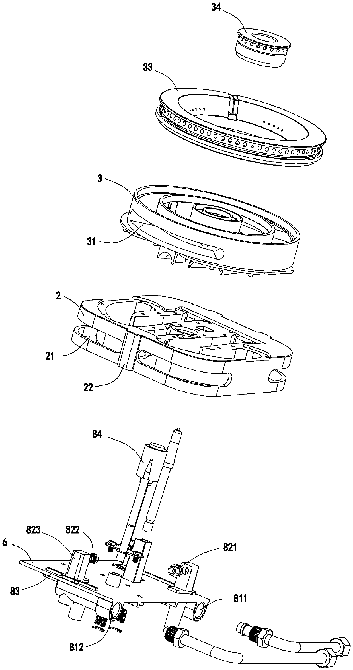
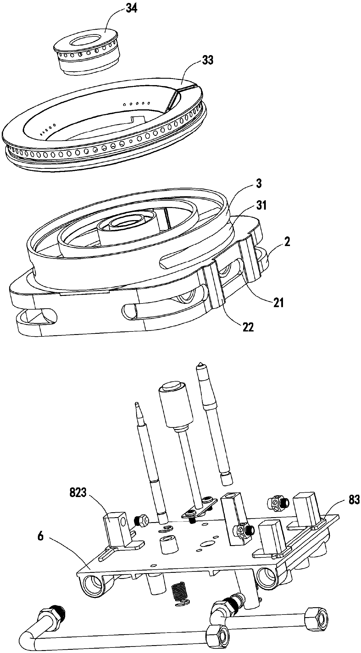
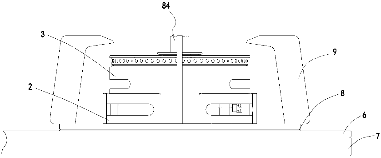
[0044] refer to Figure 1-23 , a gas cooker, including a bottom case 7, a panel 6, a fixed plate 8 and a pot support 9 from bottom to top, and a burner is installed above the fixed plate 8.

[0045] refer to Figure 11-23 , the burner includes an upper body 3 and a lower body 2, the upper body 3 is a roughly annular head cavity, the upper periphery of...


PUM


Abstract

The invention discloses a gas cooker. The gas cooker comprises a bottom shell, a panel, a fixed disc and a pot bracket, and a burner is mounted above the fixed disc. The bottom surface of the panel isprovided with a gas inlet passage, the upper surface of the panel is provided with a nozzle, and the nozzle is disposed opposite to a gas inlet on the burner. A primary air intake groove for the inflow of air is formed in the burner, and the primary air intake groove is located above the fixed disc. The burner includes an upper portion body and a lower portion body, the upper portion body is integrally casted to form three pipe-like protrusions, and the lower portion body is integrally casted to form three pipe-like depressions. After being combined, a first external fire ejector, an inner fire ejector and a second external fire which are horizontally arranged in an adjacent mode are formed. According to the gas cooker, the burner is installed above the fixed disc, and the air required for combustion comes from the upper portion of the panel. The mixing effect of gas and the air is good, the combustion effect is good, and the combustion power is large. The burner is formed by rivetingand connecting the upper portion body and the lower portion body which are integrally casted, the manufacturing process is simple, the ejector coefficient is large, the combustion effect is good, andthe hygienic property is good.

Description

technical field [0001] The invention belongs to the field of gas cookers, in particular to a gas cooker in which gas and air are mixed uniformly and sufficiently. Background technique [0002] The burners currently on the market usually have a primary air intake slot located below the panel. The primary air intake effect of this structure is relatively unstable, and the mixing effect of gas and air is not good, resulting in insufficient combustion of gas and low power of the burner. , poor combustion effect. [0003] An important factor affecting the working efficiency of the gas burner is whether the mixture of gas and air is sufficient or not, so the design of the ejector is very important. In order to improve the ejection coefficient, the ejectors currently on the market usually set the ejector long outside the base, or set the ejector inside the base, and set an arc-shaped mixing chamber at the end of the ejector tube to eject The pipe and the mixing chamber are extend...

Claims


Application Information

Patent Timeline
Patent Type & Authority Patents(China)
IPC IPC(8): F23D14/06F23D14/64
CPCF23D14/06F23D14/64
Inventor 傅福华
Owner SHENGZHOU FUHUA GAS APPLIANCE
Why Eureka
Try Eureka