Crack size detection equipment for geological disaster prevention

A technology of geological disasters and detection equipment, which is applied in the direction of measuring devices, instruments, etc., can solve the problems of inaccurate detection and no reminder function

Active Publication Date: 2018-07-27
江西核工业建设有限公司
View PDF12 Cites 3 Cited by
  • Summary
  • Abstract
  • Description
  • Claims
  • Application Information

AI Technical Summary

Problems solved by technology

[0005] In order to overcome the shortcomings of inaccurate detection and no reminder function in the prior art, the technical problem to be solved by the present invention is to provide a crack size detection device for geological disaster prevention with accurate detection and reminder function

Method used


Image

  • Crack size detection equipment for geological disaster prevention
  • Crack size detection equipment for geological disaster prevention
  • Crack size detection equipment for geological disaster prevention

Examples


Embodiment 1

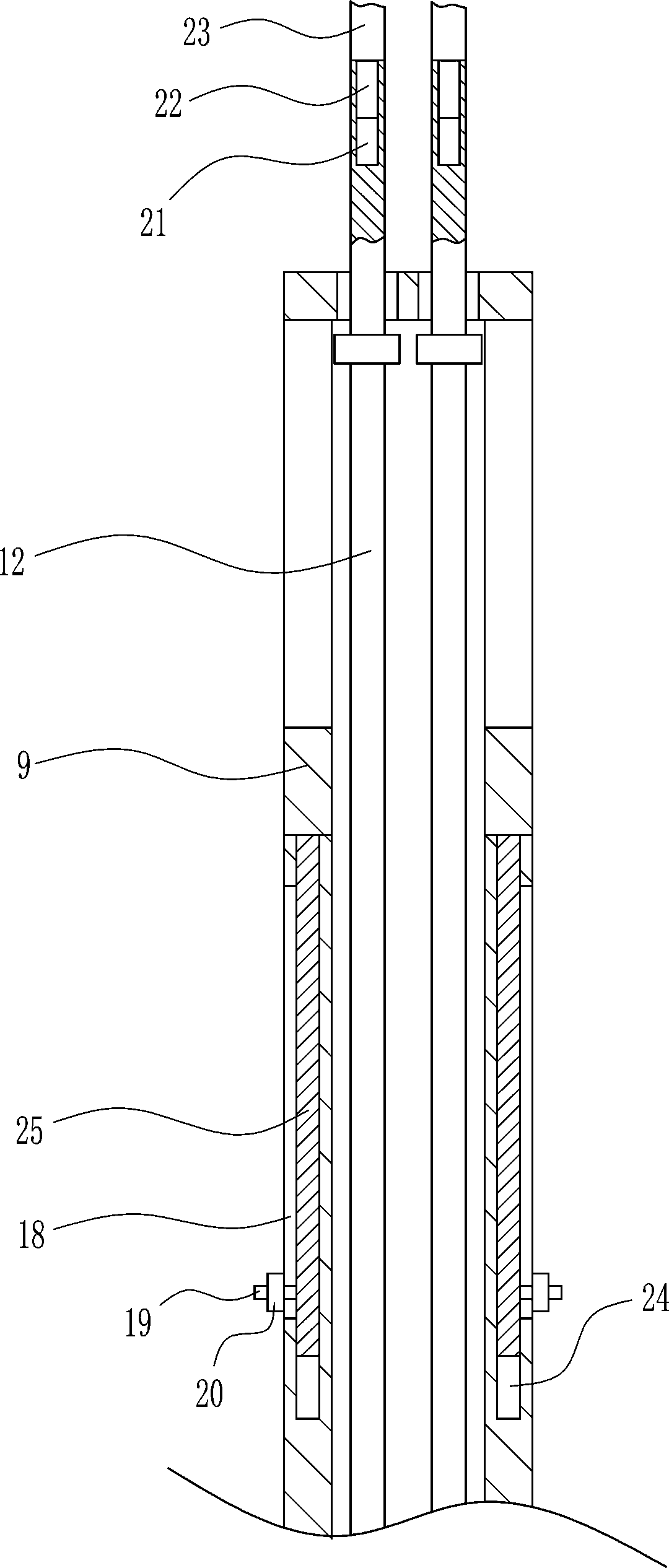
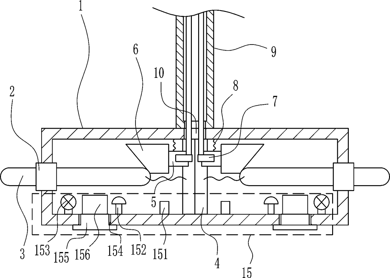
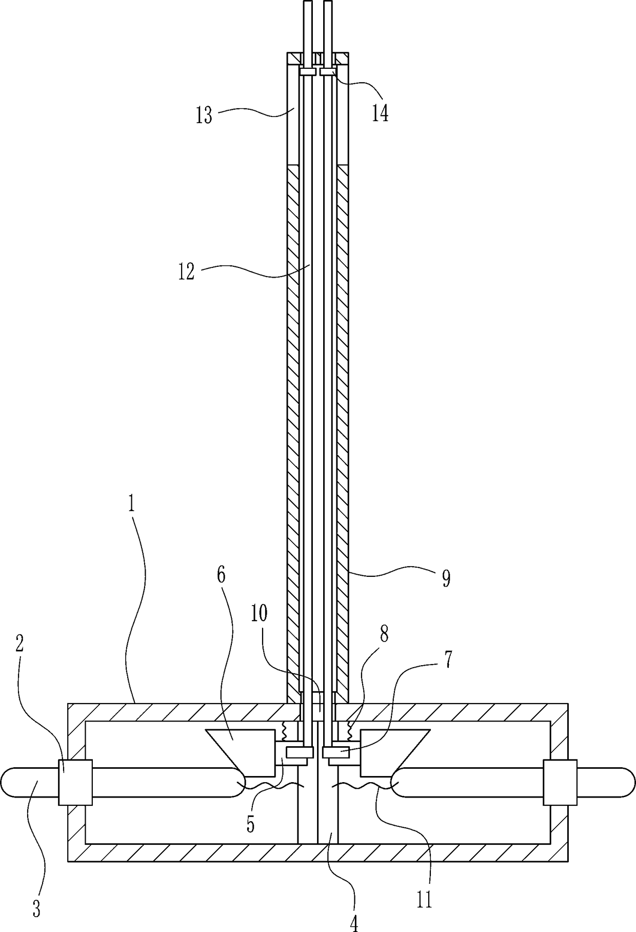
[0027] A crack size detection device for geological disaster prevention, such as Figure 1-5 As shown, it includes cylinder 1, guide sleeve 2, guide rod 3, first slide rail 4, first slide block 5, wedge block 6, stop block 7, first spring 8, hollow tube 9, first screw rod 12 And the first nut 14, the middle part of the left and right walls of the cylinder 1 is provided with a guide sleeve 2, the guide sleeve 2 is sleeved with a guide rod 3, the front and rear sides of the left guide rod 3 and the front and rear of the first slide rail 4 on the left The second spring 11 is connected between the middle part of the front side, the second spring 11 is connected between the left part of the front and rear sides of the guide rod 3 on the right side and the front and back middle part of the first slide rail 4 on the right side, and the middle part of the cylinder 1 The first sliding rail 4 is arranged symmetrically on the left and right, and the first sliding block 5 is slidably conn...

Embodiment 2

[0029] A crack size detection device for geological disaster prevention, such as Figure 1-5 As shown, it includes cylinder 1, guide sleeve 2, guide rod 3, first slide rail 4, first slide block 5, wedge block 6, stop block 7, first spring 8, hollow tube 9, first screw rod 12 And the first nut 14, the middle part of the left and right walls of the cylinder 1 is provided with a guide sleeve 2, the guide sleeve 2 is sleeved with a guide rod 3, the front and rear sides of the left guide rod 3 and the front and rear of the first slide rail 4 on the left The second spring 11 is connected between the middle part of the front side, the second spring 11 is connected between the left part of the front and rear sides of the guide rod 3 on the right side and the front and back middle part of the first slide rail 4 on the right side, and the middle part of the cylinder 1 The first sliding rail 4 is arranged symmetrically on the left and right, and the first sliding block 5 is slidably connec...

Embodiment 3

[0032] A crack size detection device for geological disaster prevention, such as Figure 1-5 As shown, it includes cylinder 1, guide sleeve 2, guide rod 3, first slide rail 4, first slide block 5, wedge block 6, stop block 7, first spring 8, hollow tube 9, first screw rod 12 And the first nut 14, the middle part of the left and right walls of the cylinder 1 is provided with a guide sleeve 2, the guide sleeve 2 is sleeved with a guide rod 3, the front and rear sides of the left guide rod 3 and the front and rear of the first slide rail 4 on the left The second spring 11 is connected between the middle part of the front side, the second spring 11 is connected between the left part of the front and rear sides of the guide rod 3 on the right side and the front and back middle part of the first slide rail 4 on the right side, and the middle part of the cylinder 1 The first sliding rail 4 is arranged symmetrically on the left and right, and the first sliding block 5 is slidably conn...


PUM


Abstract

The invention relates to detection equipment, in particular to crack size detection equipment for geological disaster prevention. The to-be-solved technical problem is to provide the crack size detection equipment for the geological disaster prevention with functions of accurate detecting and reminding. The invention provides the crack size detection equipment for geological disaster prevention, the equipment comprises a cylinder, a guide sleeve, a guide rod, a first sliding rail, a first sliding block and the like; the guide sleeve is arranged in the middle of the left and right walls of thecylinder, the guide rod is sleeved with the guide sleeve, and a second spring is connected between the right portion of the front and back sides of the guide rod at the left side of the equipment andthe middle of the front and back sides of the first sliding rail at the left side of the equipment. The crack size detection equipment for the geological disaster prevention has the advantages that the effects of accurate detection and reminding function are achieved, the position measured by the guide rod is fixed through a first nut so that the measurement of the guide rod is more accurate, a lighting device and a reminding device can allow a user to observe cracks and remind the user to prevent the occurrence of unmeasured results, and a first threaded rod and a second threaded rod cooperate so that the equipment can measure deeper positions.

Description

technical field [0001] The invention relates to a detection device, in particular to a crack size detection device for geological disaster prevention. Background technique [0002] Geological hazards, a professional term in geology, refer to geological processes (phenomena) that are formed under the action of natural or human factors and cause damage and loss to human life, property and the environment. Such as collapse, landslide, debris flow, ground fissure, soil erosion, land desertification and swamp, soil salinization, and earthquake, volcano, geothermal damage, etc. In order to prevent geological disasters and make preparations in time, what needs to be done for geological disasters such as ground fissures and landslides is to measure the distance between the cracks and see if the land on both sides of the cracks has moved too long, but the current detection equipment is not very good. Accurate, and there is no reminder function. [0003] To sum up, it is necessary t...

Claims


Application Information

Patent Timeline
IPC IPC(8): G01B21/00G01B21/16
CPCG01B21/00G01B21/16
Inventor 王丽莉钟玉清刘育铭
Owner 江西核工业建设有限公司
Why Eureka
Try Eureka