Pulse detection method and device

A pulse detection and pulse technology, applied in the field of mass spectrometry, can solve the problems of signal detection and processing difficulty, inability to identify ion peaks, inaccurate detection results, etc., to achieve fast and accurate adjustment, reduce bandwidth, and reduce costs.

Active Publication Date: 2021-02-12
FOCUSED PHOTONICS +2
View PDF7 Cites 0 Cited by
  • Summary
  • Abstract
  • Description
  • Claims
  • Application Information

AI Technical Summary

Problems solved by technology

In general, a pulse signal is generated by one ion, but in practical applications, not all ions reach the detector in sequence, that is, not all ion peaks are arranged in sequence. In many cases, especially when the sample concentration is relatively When it is high, many ions arrive at the detector very close to each other, so the formed ion peaks overlap, and a pulse signal does not represent an ion, which causes great difficulty in signal detection and processing.
There is also a situation where the ion peaks themselves do not overlap, but the overlapping peaks are caused during the signal amplification process, and finally the two ion peaks cannot be identified, resulting in pulse loss and inaccurate detection results

Method used


Image

  • Pulse detection method and device
  • Pulse detection method and device
  • Pulse detection method and device

Examples


Embodiment 1

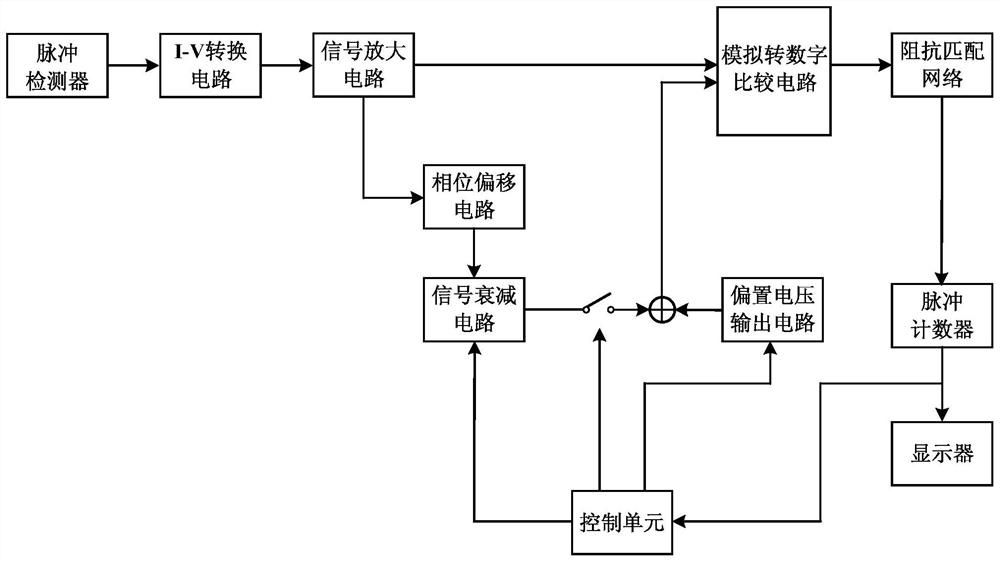
[0041] figure 1 Schematically provides a schematic diagram of the circuit structure of the pulse detection device of this embodiment, as figure 1 Shown: the pulse detection device includes:

[0042] Pulse detector, I-V conversion circuit, signal amplification circuit, impedance matching network, pulse counter and display connected in sequence:

[0043] A phase shift circuit, the input end of the phase shift circuit is connected to the output end of the signal amplification circuit for phase shift of the analog signal;

[0044] A signal attenuation circuit, the input end of the signal attenuation circuit is connected to the phase shift circuit, and the output end is connected to a switch for attenuation of the analog signal;

[0045] a switch, the switch is arranged between the signal attenuation circuit and the bias voltage output circuit;

[0046] The bias voltage output circuit is used to output the bias voltage, and the bias voltage is superimposed with the offset and at...

Embodiment 2

[0067] This embodiment is an application example of the pulse detection device in Embodiment 1 of the present invention on a mass spectrometer.

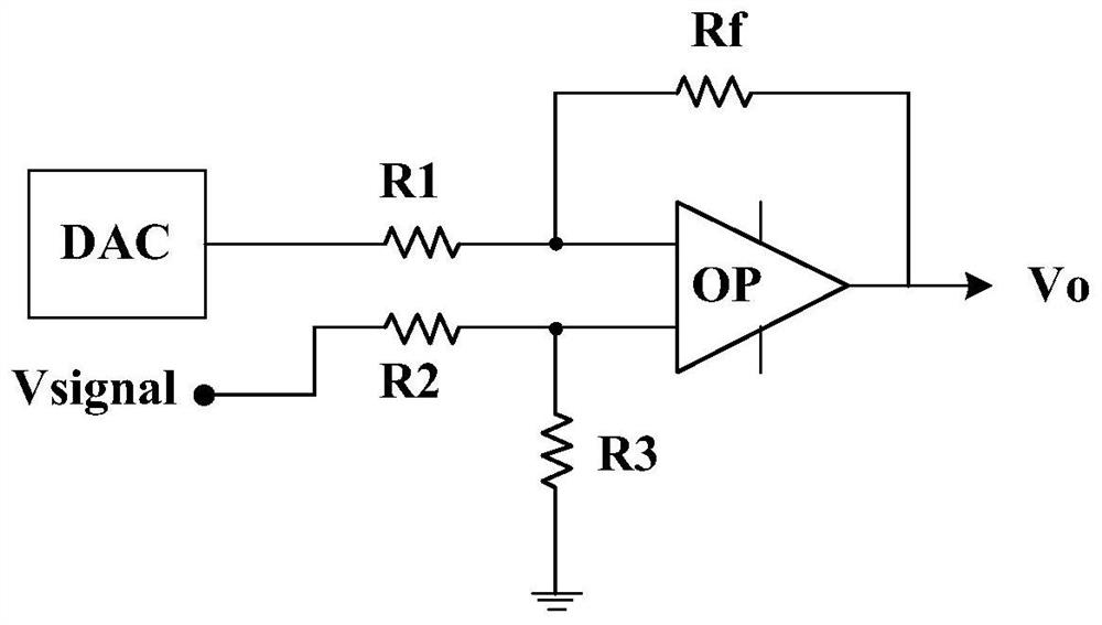
[0068] In this application example, in order to avoid the impact of the instantaneous high voltage generated when the pulse detector is turned on, an overvoltage protection circuit is set between the pulse detector and the I-V conversion circuit; the phase shift circuit is a capacitor, and the signal attenuation circuit includes digital analog-to-analog converters, operational amplifiers, and resistors such as figure 2 Shown), the attenuation range can be adjusted by controlling the DAC through the control unit (using MCU).

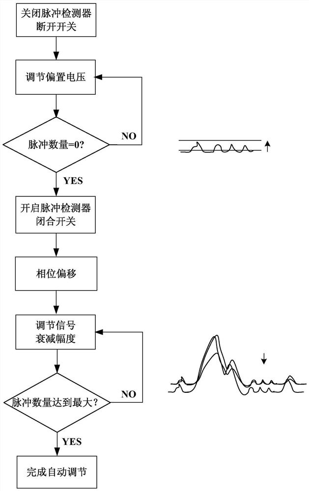
[0069] image 3 Schematically shows the pulse detection automatic adjustment flow chart, such as image 3 As shown, the automatic adjustment process of the pulse detection device is as follows:

[0070] S1. Turn off the pulse detector, turn off the switch, and gradually increase the bias voltage from 0V, and...


PUM


Abstract

The invention relates to a pulse detection method and device. The pulse detection method comprises the following steps: (A1) turning on the pulse detector to collect the original analog signal; (A2) performing phase shift on the analog signal; (A3) converting the analog signal to Carrying out signal attenuation; (A4) superimposing a bias voltage, the bias voltage being greater than or equal to the maximum value of the noise signal; (A5) comparing the original analog signal with the analog signal processed by the above steps, and obtaining the pulse by pulse counting quantity. The invention has the advantages of stable detection signal, no pulse loss, automatic adjustment of pulse detection and the like.

Description

technical field [0001] The invention relates to the field of mass spectrometry analysis, in particular to a pulse detection method and device applied to a mass spectrometer pulse detector. Background technique [0002] Pulse detectors are widely used in the ion detection of mass spectrometers, and the number of ions arriving at the entrance of the detector is obtained by detecting the number of analog pulses output by the pulse detector. When an ion hits the pulse detector, the detector will correspondingly output a small pulse current signal, usually tens of nA to tens of uA, and the pulse width is tens of nS. In general, a pulse signal is generated by one ion, but in practical applications, not all ions reach the detector in sequence, that is, not all ion peaks are arranged in sequence. In many cases, especially when the sample concentration is relatively When it is higher, many ions arrive at the detector very close to each other, so the formed ion peaks overlap, and one...

Claims


Application Information

Patent Timeline
Patent Type & Authority Patents(China)
IPC IPC(8): G01R29/02
CPCG01R29/02
Inventor 杨继伟张建钱隆李纲
Owner FOCUSED PHOTONICS
Why Eureka
Try Eureka