Foresight scanning radar super-resolution imaging method based on splitting Bregman

A technology of super-resolution imaging and scanning radar, which is applied in the direction of radio wave reflection/re-radiation, utilization of re-radiation, measurement devices, etc. It can solve the problems of low resolution, inability to meet the high-resolution requirements of target azimuth, and inability to distinguish multiple targets, etc. , to improve the azimuth resolution

Inactive Publication Date: 2018-07-27
UNIV OF ELECTRONIC SCI & TECH OF CHINA
View PDF3 Cites 11 Cited by
  • Summary
  • Abstract
  • Description
  • Claims
  • Application Information

AI Technical Summary

Problems solved by technology

The existing forward-looking scanning radar achieves high resolution in the range direction by transmitting a chirp signal with a large time-width-bandwidth product and performing matched filtering on the echo. high resolution requirement
[0003] Aiming at the problem of low azimuth resolution of forward-looking scanning radar imaging, the document "S.M.Sherman and D.K.Barton, Monopulse principles and techniques. Artech House, 2011." proposed a method using monopulse technology to achieve azimuth detection of a single target. High resolution, but this method cannot distinguish multiple targets in the same lobe; document "A new Sector Imaging Radar for Enhanced Vision-SIREV" (SPIEConference on Enhanced and Synthetic Vision, 1999,

Method used


Image

  • Foresight scanning radar super-resolution imaging method based on splitting Bregman
  • Foresight scanning radar super-resolution imaging method based on splitting Bregman
  • Foresight scanning radar super-resolution imaging method based on splitting Bregman

Examples


Embodiment Construction

[0043] In order to facilitate those skilled in the art to understand the technical content of the present invention, the content of the present invention will be further explained below in conjunction with the accompanying drawings.

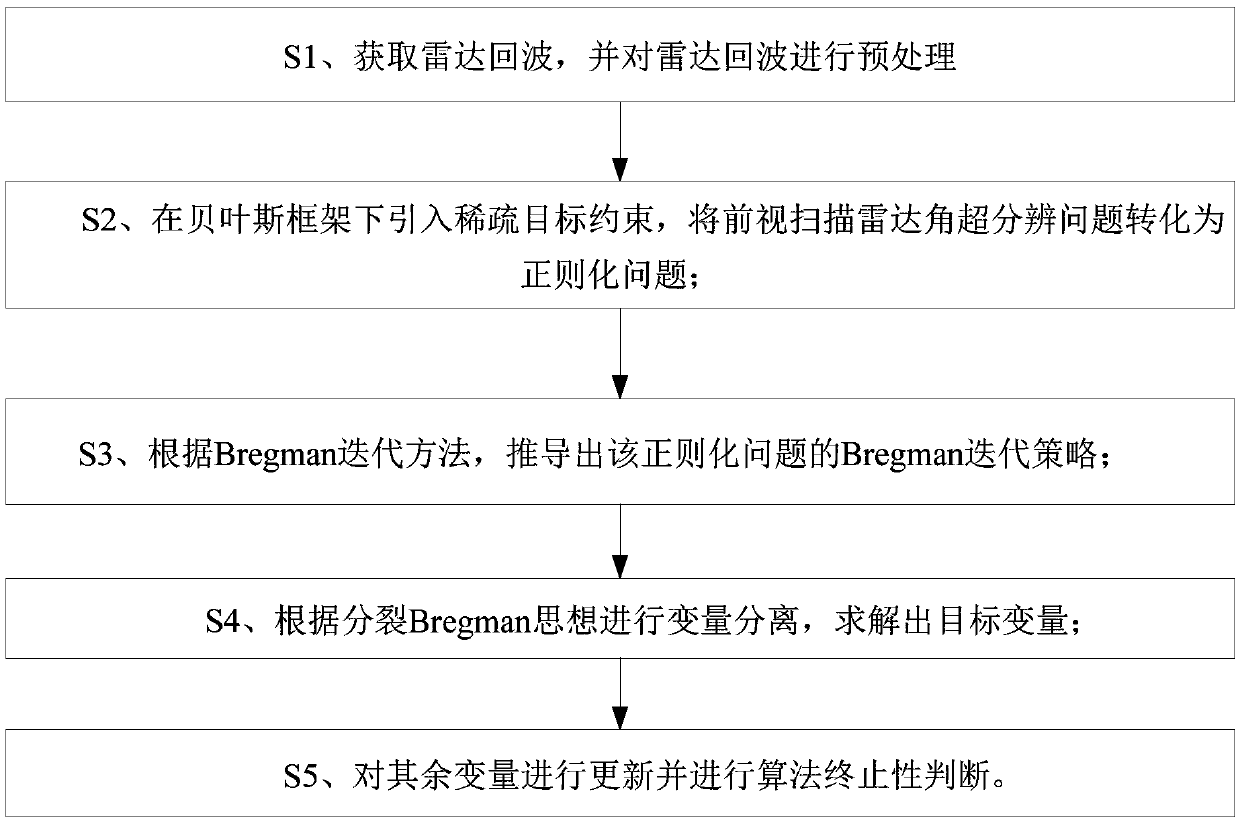
[0044] Such as figure 1 Shown is the scheme block diagram of the present invention, and technical scheme of the present invention is: based on splitting Bregman's forward-looking scanning radar super-resolution imaging method, comprising:

[0045] S1. Obtain the radar echo, improve the range resolution through range pulse compression, and then perform range walking correction on the echo, and model the range walking corrected echo as the convolution form of the antenna pattern and the target scattering coefficient;

[0046] S2. Introduce sparse target constraints under the Bayesian framework, and transform the forward-looking scanning radar angle super-resolution problem into L 1 regularization problem;

[0047] S3. According to the Bregman ite...


PUM


Abstract

The invention discloses a foresight scanning radar super-resolution imaging method based on splitting Bregman. The foresight scanning radar super-resolution imaging method is applied to the technicalfield of radar imaging. By introducing the sparse goal constraint under a Bayes framework, the foresight scanning radar angular super-resolution problem is converted into the L1 regularization problem; then according to the Bregman iteration method, a Bregman iteration strategy of the L1 regularization problem is derived; then according to the splitting Bregman thought, variable separation is conducted, and the target variable is solved; finally, the rest variables are updated, algorithm terminal judgment is conducted, and through crossed iteration, the azimuth resolution is increased.

Description

technical field [0001] The invention belongs to the technical field of radar imaging, in particular to an airborne forward-looking scanning radar azimuth super-resolution technology. Background technique [0002] Radar has all-weather and all-weather working capabilities. The realization of high-resolution imaging of targets in the forward-looking area of ​​airborne radar is of great significance for improving pilots' ability to observe the front area, guiding weapons to accurately strike targets, and implementing airborne security. This requires airborne radar At the same time, it has high resolution capabilities in both range and azimuth directions. The existing forward-looking scanning radar achieves high resolution in the range direction by transmitting a chirp signal with a large time-width-bandwidth product and performing matched filtering on the echo. High resolution requirements. [0003] Aiming at the problem of low azimuth resolution of forward-looking scanning r...

Claims


Application Information

Patent Timeline
IPC IPC(8): G01S13/89G01S7/41
CPCG01S7/41G01S13/89
Inventor 张寅张启平张永伟聂宪波张永超毛德庆黄钰林杨建宇郭德明庄龙
Owner UNIV OF ELECTRONIC SCI & TECH OF CHINA
Why Eureka
Try Eureka