Light-borne ultra-broadband long-range microwave photon chaotic mimo imaging radar

A technology of microwave photon and imaging radar, which is applied in the directions of electromagnetic wave re-radiation, radio wave measurement system, utilization of re-radiation, etc. It can solve the problems of remote control of radar and enhance the broadband of transmitted signals, etc., achieve ingenious design and improve resolution , to achieve high-resolution effects

Active Publication Date: 2017-06-09
TAIYUAN UNIV OF TECH
View PDF6 Cites 0 Cited by
  • Summary
  • Abstract
  • Description
  • Claims
  • Application Information

AI Technical Summary

Problems solved by technology

But it also has a difficult problem that needs to be solved urgently: how to conveniently and quickly generate a quasi-orthogonal signal set with unlimited waveform number and code length as the transmission signal of MIMO radar and how to enhance the broadband of the transmission signal
In 2004, Liu et al. at the University of California, Los Angeles proposed a chaotic radar system based on light injection semiconductor lasers, which achieved a distance resolution of 9cm, but the radar did not achieve remote control.
However, there is currently no MIMO radar that can directly generate multiple, quasi-orthogonal chaotic UWB signals in the optical domain

Method used


Image

  • Light-borne ultra-broadband long-range microwave photon chaotic mimo imaging radar

Examples


Embodiment Construction

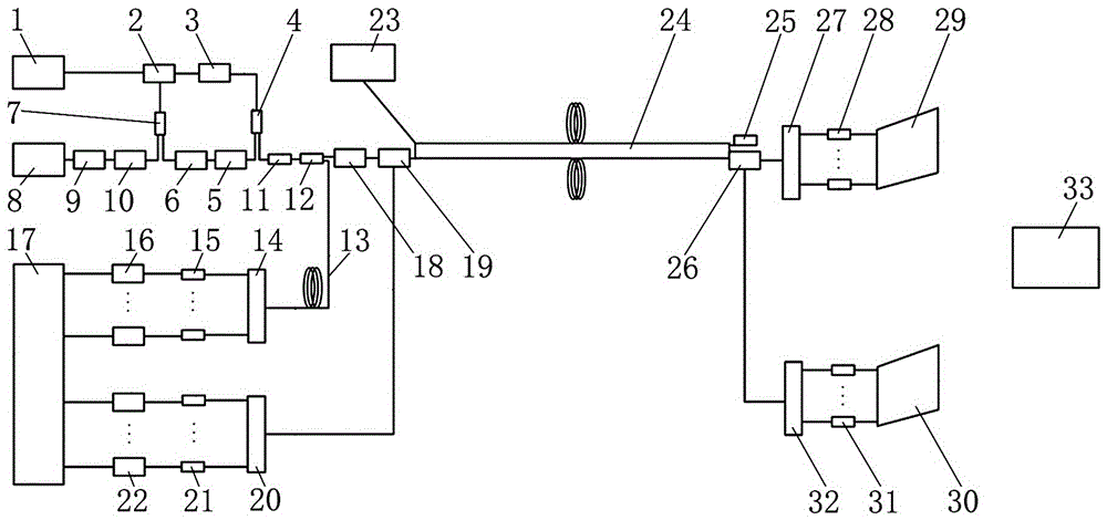
[0025] Light-borne ultra-broadband long-range microwave photon chaos MIMO imaging radar, including central station part, transmission link part and base station part;

[0026] The central station part includes a first multi-longitudinal mode semiconductor laser 1 with a fiber feedback loop, a first optical circulator 2, a first erbium-doped fiber amplifier 3, a 1×2 20:80 coupler 4, a first polarization Controller 5, first adjustable optical attenuator 6, 2×1 50:50 coupler 7, second multi-longitudinal mode semiconductor laser with fiber feedback loop 8, second adjustable optical attenuator 9, second Polarization controller 10, optical isolator 11, 1×2 10:90 coupler 12, optical delay line 13, first arrayed waveguide grating 14, first photodetector group 15, first analog-to-digital converter 16, digital Signal acquisition and processing module 17, second erbium-doped fiber amplifier 18, second optical circulator 19, second arrayed waveguide grating 20, second photodetector group ...


PUM


Abstract

The invention relates to the radar imaging technology, and concretely relates to radio-over-fiber ultra-wideband remote microwave photon chaotic MIMO imaging radar. The invention helps to solve the problem that there is no MIMO radar that can generate multi-path, quasi-orthogonal chaotic ultra-wideband signals directly in an optical domain. The radio-over-fiber ultra-wideband remote microwave photon chaotic MIMO imaging radar includes a central station part, a transmission link part and a base station part. The central station part includes a first multi-longitudinal mode semiconductor laser with a fiber feedback loop, a first optical circulator, a first erbium doped fiber amplifier, a 1*2 20: 80 coupler, a first polarization controller, a first variable optical attenuator, a 2*1 50:50 coupler, a second multi-longitudinal mode semiconductor laser with a fiber feedback loop, a second variable optical attenuator, a second polarization controller, and an optical isolator. The radar is suitable for remotely monitoring, in real time and with high resolution, targets in battle fields, snow mountain tops, islands, coal bunkers and other severe environments.

Description

technical field [0001] The invention relates to radar imaging technology, in particular to an optical-carrying ultra-broadband long-range microwave photon chaos MIMO imaging radar. Background technique [0002] With the advancement of radar technology, the radar function has already developed from the initial target detection, ranging, angle measurement, speed measurement, etc. to two-dimensional or three-dimensional target imaging. Radar images can help people obtain useful information about the target's spatial structure and attribute characteristics. Since the 1950s, radar imaging technology has been widely used in many fields such as agricultural and forestry production, environmental protection, disaster reporting, marine monitoring, geographic mapping, resource exploration, non-destructive testing, biomedicine, archaeology and military affairs. [0003] Radar imaging technology is to retrieve the target image by actively transmitting electromagnetic waves to the targe...

Claims


Application Information

Patent Timeline
Patent Type & Authority Patents(China)
IPC IPC(8): G01S17/89
CPCG01S17/89
Inventor 张明江徐航刘慧王冰洁刘丽王云才
Owner TAIYUAN UNIV OF TECH
Why Eureka
Try Eureka