
Rotor structure, permanent magnet assisted synchronous reluctance motor and electric vehicle

A rotor structure and permanent magnet technology, applied in electric vehicles, motors, electric components, etc., can solve problems such as low motor efficiency, and achieve the effects of improving efficiency, optimizing magnetic circuits, and improving material utilization.

Active Publication Date: 2019-12-13
GREE ELECTRIC APPLIANCES INC +1
View PDF5 Cites 0 Cited by
  • Summary
  • Abstract
  • Description
  • Claims
  • Application Information

AI Technical Summary

Problems solved by technology

[0003] The main purpose of the present invention is to provide a rotor structure, permanent magnet assisted synchronous reluctance motor and electric vehicle, to solve the problem of low motor efficiency in the prior art

Method used


Image

  • Rotor structure, permanent magnet assisted synchronous reluctance motor and electric vehicle
  • Rotor structure, permanent magnet assisted synchronous reluctance motor and electric vehicle
  • Rotor structure, permanent magnet assisted synchronous reluctance motor and electric vehicle

Examples


Embodiment Construction

[0028] It should be noted that the embodiments in the application and the features in the embodiments can be combined with each other if there is no conflict. Hereinafter, the present invention will be described in detail with reference to the drawings and in conjunction with the embodiments.

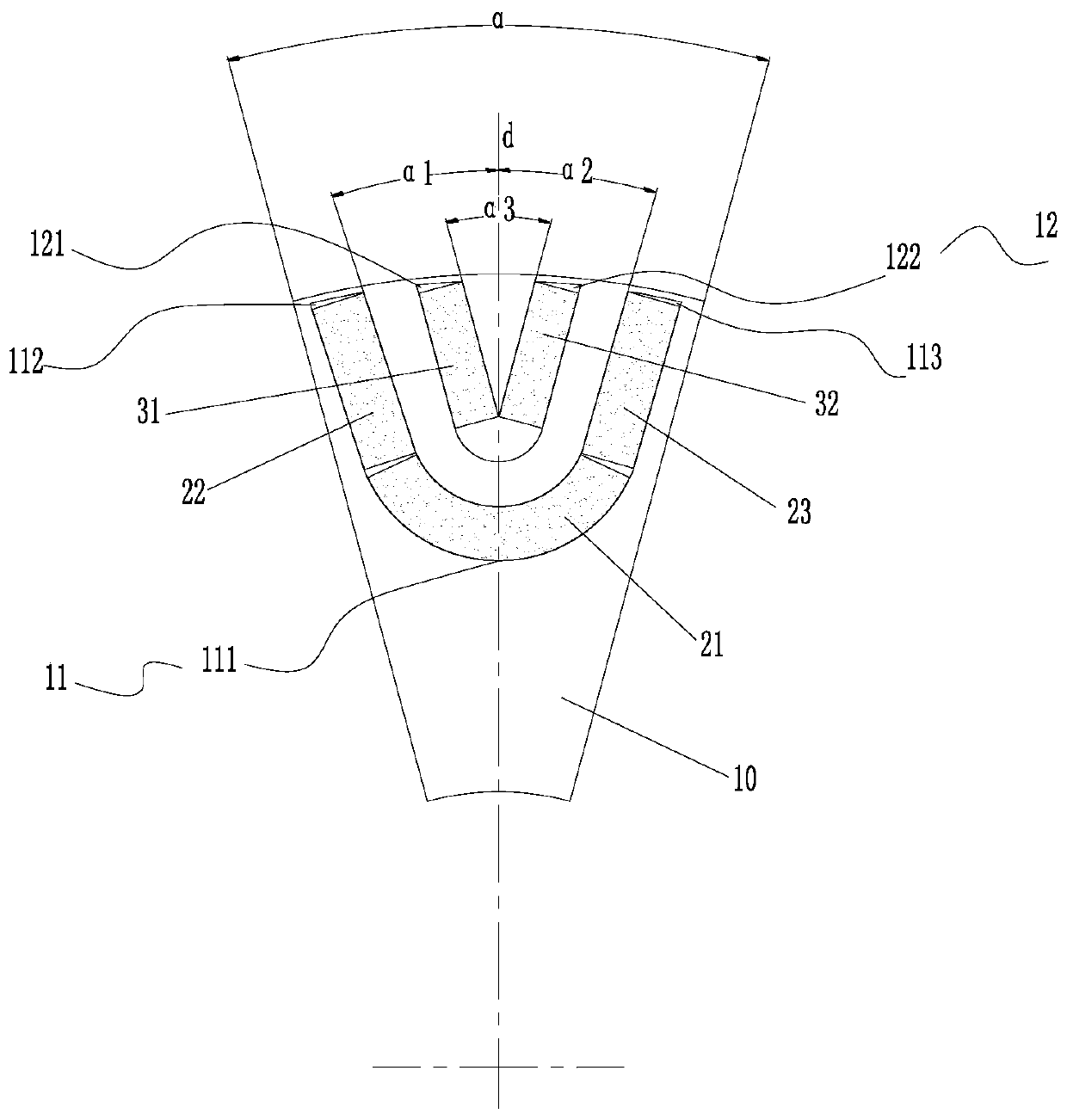
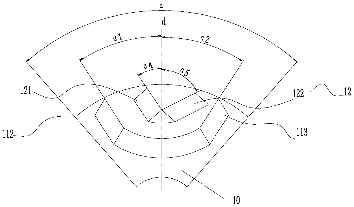
[0029] Combine Figure 1 to Figure 5 As shown, according to an embodiment of the present invention, a rotor structure is provided.

[0030] Specifically, such as figure 1 As shown, the rotor structure includes a rotor body 10. The rotor body 10 is provided with an inner layer permanent magnet slot 11 and an outer layer permanent magnet slot 12. A magnetic channel is formed between the inner layer permanent magnet slot 11 and the outer layer permanent magnet slot 12, and the inner layer permanent magnet slot 11 runs along the rotor body The cross section in the radial direction of 10 has a U-shaped structure, and the cross section of the outer permanent magnet slot 12 in the radial directio...


PUM


Abstract

The invention provides a rotor structure, a permanent magnet assisted synchronous reluctance motor and an electric vehicle. The rotor structure includes a rotor body. The rotor body is provided with an inner permanent magnet slot and an outer permanent magnet slot. The inner permanent magnet slot and the outer permanent magnet slot A magnetic conduction channel is formed between the permanent magnet slots of the layer, the cross section of the inner permanent magnet slot along the radial direction of the rotor body is U-shaped, and the outer permanent magnet slot along the radial direction of the rotor body is V-shaped. structure. Such arrangement can effectively utilize the material of the rotor body, and at the same time optimize the magnetic circuit of the rotor body. The material utilization rate of the rotor is effectively improved, and the efficiency of the motor with the rotor structure is effectively improved at the same time.

Description

Technical field [0001] The invention relates to the technical field of electrical equipment, in particular to a rotor structure, a permanent magnet auxiliary synchronous reluctance motor and an electric vehicle. Background technique [0002] In the prior art, due to the improper arrangement of the permanent magnet slots on the rotor, the effective utilization rate of the rotor material is reduced, resulting in the problems of increased motor rotation and low motor efficiency in the prior art. Summary of the invention [0003] The main purpose of the present invention is to provide a rotor structure, a permanent magnet auxiliary synchronous reluctance motor and an electric vehicle to solve the problem of low motor efficiency in the prior art. [0004] In order to achieve the above objective, according to one aspect of the present invention, a rotor structure is provided, including: a rotor body, the rotor body is provided with an inner layer permanent magnet slot and an outer layer p...

Claims


Application Information

Patent Timeline
Patent Type & Authority Patents(China)
IPC IPC(8): H02K1/27H02K29/03
CPCH02K1/27H02K29/03H02K2201/06H02K2213/03H02K1/2773Y02T10/64
Inventor 周博胡余生陈彬肖勇
Owner GREE ELECTRIC APPLIANCES INC
Learn More