A loudspeaker magnetic circuit system

A technology of magnetic circuit system and loudspeaker, applied in the direction of sensors, electrical components, etc., can solve the problem that the influence of magnetic declination angle of magnetic steel on the magnetic circuit of the loudspeaker cannot be effectively considered, a single magnetic declination angle, or no magnetic declination angle, the use of magnetic steel rate reduction and other problems, to increase the cost, optimize the magnetic circuit, and increase the magnetic field strength.

Active Publication Date: 2021-09-28
湖南航天磁电科技有限公司
View PDF12 Cites 0 Cited by
  • Summary
  • Abstract
  • Description
  • Claims
  • Application Information

AI Technical Summary

Problems solved by technology

[0003] At present, the design of the magnetic circuit of the loudspeaker mainly focuses on the optimization of its own structure. For example, the outer diameter of the magnetic upper and lower plates is as close as possible to the outer diameter of the magnetic steel to improve the utilization of the magnetic steel, or the thickness of the magnetic lower plate is reduced. Increase the stroke of the voice coil, but this design will cause the utilization rate of the magnet to decrease due to the magnetic saturation of the magnetic lower plate
In this type of design, it is often simply considered that the magnetic steel has a single magnetic declination, or there is no magnetic declination (the magnetic declination is 0°).
There is a change in the magnetic declination angle of the ring magnet from the inner diameter to the outer diameter section, and the magnetic declination angle increases significantly near the outer diameter. Therefore, the magnetic steel is considered as a single magnetic declination angle, or there is no magnetic declination angle. The magnetic field distribution of the magnetic steel is undoubtedly inconsistent, and this type of design cannot effectively consider the influence of the magnetic steel magnetic declination on the speaker's magnetic circuit

Method used


Image

  • A loudspeaker magnetic circuit system
  • A loudspeaker magnetic circuit system
  • A loudspeaker magnetic circuit system

Examples


Embodiment 1

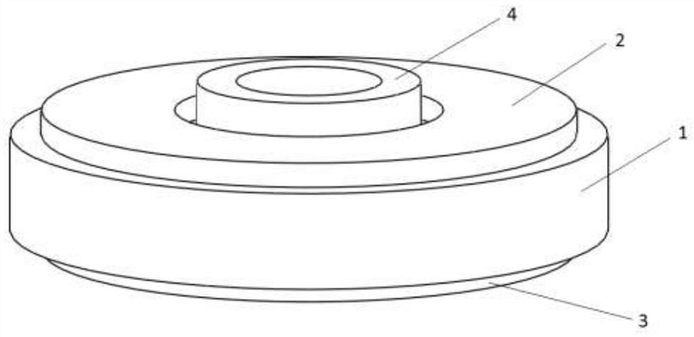
[0020] refer to Figure 1-3 , the present embodiment includes a magnetic steel 1, a magnetic upper plate 2, a magnetic lower plate 3 and a magnetic column 4; the magnetic steel 1 is an annular magnetic steel, the magnetic upper plate 2 and the magnetic lower plate 3 are annular plates, The magnetic upper plate 2 is arranged on the upper end surface of the annular magnetic steel, the magnetic lower plate 3 is arranged on the lower end surface of the annular magnetic steel, and the magnetically conductive column 4 is arranged in the center hole of the annular magnetic steel, and the magnetic upper plate 2 or the magnetically conductive The lower plate 3 is fixedly connected. In this embodiment, the magnetically conductive column 4 is connected with the magnetically conductive lower plate 3 as a whole. The central axes of the magnetic steel 1 , the magnetic upper plate 2 , the magnetic lower plate 3 and the magnetic column 4 are coincident.

[0021] refer to Figure 5 , the ann...

Embodiment 2

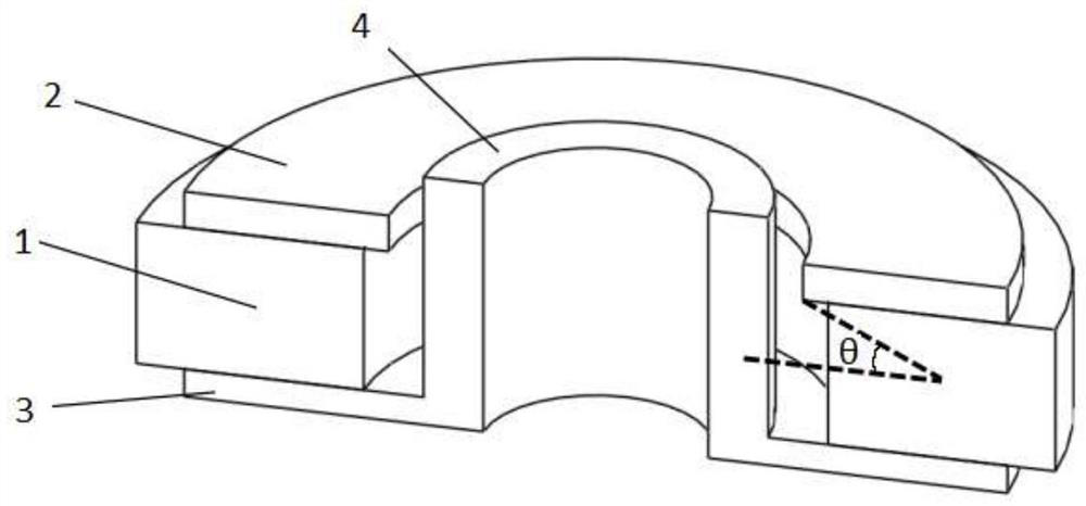
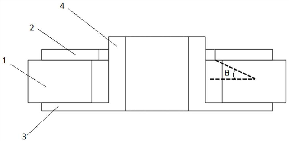
[0026] The difference between this embodiment and embodiment 1 is only: the average magnetic declination angle of the first magnetic ring 1-1 measured in this embodiment The average magnetic declination of the second magnetic ring 1-2 The average magnetic declination angle of the third magnetic ring 1-3 The average magnetic declination of the fourth magnetic ring 1-4 k 1 =0.25,k 2 =0.29,k 3 =0.26,k 4 =0.20, the angle between the magnetic upper plate 2 and the magnetic steel 1 The included angle θ is defined as: a virtual central circle A at the center between the inner diameter surface and the outer diameter surface of the annular magnetic steel, and a distance between the circle B where the bottom end of the inner diameter surface of the magnetic permeable upper plate 2 is located and the central circle A The connection line, the angle between the distance connection line and the end face of the ring magnet is θ, and the distance connection line refers to the conne...


PUM


Abstract

A loudspeaker magnetic circuit system, comprising a magnetic steel, a magnetically conductive upper plate, a magnetically conductive lower plate, and a magnetically conductive column; The magnetic column is set in the center hole of the annular magnet; The average magnetic declination of the ring is the average magnetic declination of the second magnetic ring. The average magnetic declination of the third magnetic ring is the average magnetic declination of the fourth magnetic ring. The angle θ is the angle between the magnetic upper plate and the magnetic steel. It is defined as: a virtual center circle is created at the center between the inner diameter surface and the outer diameter surface of the annular magnetic steel, and a distance connection line is drawn between the circle where the bottom end of the inner diameter surface of the magnetic permeable upper plate is located and the center circle, and the distance connection line and The angle between the end faces of the ring magnetic steel is θ. The present invention designs the included angle between the magnetic upper plate and the magnetic steel according to the different magnetic declination angles of the magnetic steel, so that the magnetic steel and the magnetic upper plate are better matched, and the magnetic field intensity is increased.

Description

technical field [0001] The invention relates to a loudspeaker magnetic circuit system, in particular to a loudspeaker magnetic circuit system in which the included angle between a magnetically conductive upper plate and a magnetic steel is designed according to different magnetic declination angles of the magnetic steel. Background technique [0002] The loudspeaker magnetic circuit system is a component that realizes the conversion of electric-force energy, and is an important part of the speaker to complete the process of electric-force-acoustic energy conversion. The magnetic circuit system is basically composed of four types of components, including magnetic upper plate, magnetic steel, Magnetic lower plate and magnetic column. The quality of the design of the magnetic circuit system directly affects the results of the speaker's final acoustic signal output frequency response, harmonic distortion, rated power, and energy conversion efficiency. [0003] At present, the d...

Claims


Application Information

Patent Timeline
Patent Type & Authority Patents(China)
IPC IPC(8): H04R9/02H04R9/06
CPCH04R9/025H04R9/06H04R2209/022
Inventor 陈冬阳姚锐周昊胡盛青郑自儒陈晓宇
Owner 湖南航天磁电科技有限公司
Why Eureka
Try Eureka