Encoder frequency dividing circuit

A frequency division circuit and encoder technology, applied in the direction of synchronous pulse counters, etc., can solve the problems of high cost and low stability, and achieve the effects of mature components, strong anti-interference, and reduced complexity.

Inactive Publication Date: 2018-07-27
SHENZHEN SUNFAR ELECTRIC TECH
View PDF12 Cites 2 Cited by
  • Summary
  • Abstract
  • Description
  • Claims
  • Application Information

AI Technical Summary

Problems solved by technology

[0003] The purpose of the present invention is to propose a low-cost, strong anti-interference ability, and high accuracy encoder divider for the problems of high component cost, need for software and hardware cooperation, and low stability existing in the existing encoder frequency division circuit. frequency circuit

Method used


Image

  • Encoder frequency dividing circuit
  • Encoder frequency dividing circuit

Examples


Embodiment Construction

[0018] In order to make the technical purpose, technical solution and technical effect of the present invention clearer so that those skilled in the art can understand and implement the present invention, the present invention will be further described in detail below in conjunction with the accompanying drawings and specific embodiments.

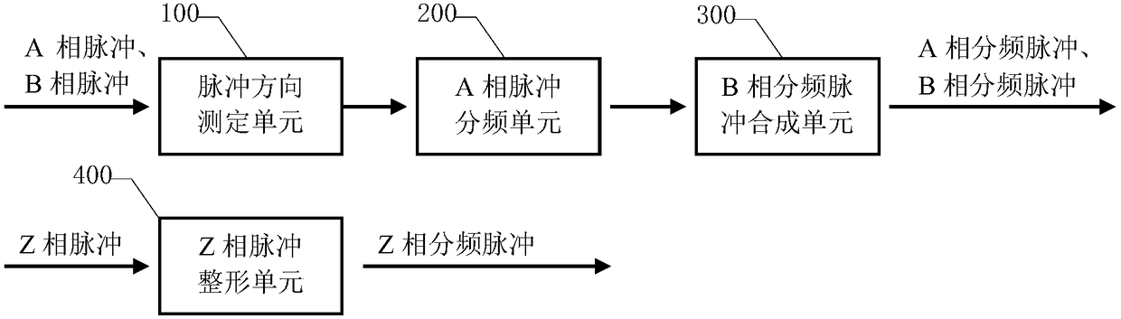
[0019] Such as figure 1 as shown, figure 1 A schematic diagram of functional modules of an encoder frequency division circuit according to an embodiment of the present invention is shown. The frequency dividing circuit of the encoder is used to divide and output the A-phase pulse, B-phase pulse and Z-phase pulse of the encoder. The frequency dividing circuit includes a pulse direction determination unit 100, a Synthesizing unit 300; Wherein, pulse direction measuring unit 100 is used for obtaining motor rotation direction according to A-phase pulse and B-phase pulse; A-phase pulse frequency division unit 200 is used for performing A-phase ...


PUM


Abstract

The invention provides an encoder frequency dividing circuit for outputting A-phase pulse, B-phase pulse and Z-phase pulse in frequency division way. The frequency dividing circuit comprises a pulse direction measuring unit, an A-phase pulse frequency dividing unit, and a B-phase frequency dividing pulse synthesis unit, wherein the pulse direction measuring unit is used for acquiring a motor rotation direction according to the A-phase pulse and the B-phase pulse; the A-phase pulse frequency dividing unit is used for performing frequency dividing counting on the A-phase pulse and the B-phase pulse according to the motor rotation direction, thereby acquiring the A-phase frequency dividing pulse; and the B-phase frequency dividing pulse synthesis unit is used for synthesizing the B-phase frequency dividing pulse which is orthogonal with the A phase frequency dividing pulse and has the consistent pulse width with that of the A phase frequency dividing pulse. The encoder frequency dividingcircuit provided by the invention has the features of being low in manufacturing cost strong in interference resistance, and high in accuracy so as to be applied and popularized in the mid and low level product.

Description

technical field [0001] The invention relates to a circuit in the field of electronic technology, more specifically, an encoder frequency division circuit. Background technique [0002] The frequency division methods of A, B, and Z phase pulses of traditional encoders mainly include MCU-based frequency division circuits, CPLD-based frequency division circuits, and FPGA-based frequency division circuits. All of the above frequency division circuits have high cost and complex peripheral circuits. , Need software and hardware to cooperate, instability and other shortcomings. Especially for medium and low-end general industrial sites, such as application scenarios such as a fixed frequency division ratio and a small frequency division ratio, the frequency division circuit is required to have the characteristics of low cost, strong anti-interference ability, and high accuracy. The A, B, and Z-phase pulse frequency division circuits of the encoder cannot meet these requirements. ...

Claims


Application Information

Patent Timeline
Patent Type & Authority Applications(China)
IPC IPC(8): H03K23/40
CPCH03K23/40
Inventor 邓智慧
Owner SHENZHEN SUNFAR ELECTRIC TECH
Why Eureka
Try Eureka