High-precision rotating encoder and measuring method of high-precision rotating encoder

A rotary encoder, high-precision technology, applied in the field of rotary encoders, can solve the problems of binary code disk manufacturing error, code channel advance or delay, output signal error, etc., achieve strong anti-pollution ability, avoid measurement error, and measure high precision effect

Active Publication Date: 2015-04-01
海宁经开产业园区开发建设有限公司
View PDF8 Cites 19 Cited by
  • Summary
  • Abstract
  • Description
  • Claims
  • Application Information

AI Technical Summary

Problems solved by technology

However, increasing the value of n will definitely cause great difficulties in the production of code discs.
At the same time, the slight manufacturing error of the binary code disc will lead to the advance or delay of individual code channels, which will cause the error of the output signal
In addition, for the circular grating encoder disk, in order to improve the subdivision accuracy of Moiré fringes, the method of increasing the density of the grating lines or placing more photosensitive elements to achieve a higher subdivision of the signal is currently more common It is to describe 50-100 grating lines in the range of 1mm, but it is impossible to accurately place multiple photosensitive elements under a certain phase difference
[0004] In general, in the current technology, due to the limitation of the grating writing technology, the accuracy of the photoelectric rotary encoder is greatly limited.

Method used


Image

  • High-precision rotating encoder and measuring method of high-precision rotating encoder
  • High-precision rotating encoder and measuring method of high-precision rotating encoder
  • High-precision rotating encoder and measuring method of high-precision rotating encoder

Examples


Embodiment 1

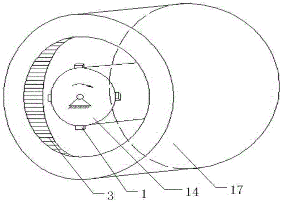
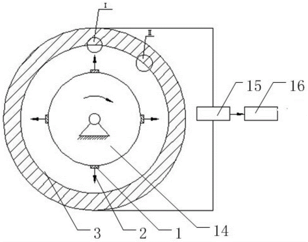
[0076] refer to Figure 1~Figure 4 , a high-precision rotary encoder, used to measure the rotation angle of the servo motor, including an optical system, a circular encoder ring 17, a rotating shaft 14, a data acquisition module 15 and a DSP data processing unit 16, the optical system includes a plurality of uniform The light source module 1 distributed on the surface of the rotating shaft 14, the circular coding ring 17 is fixed on the frame of the servo motor, the rotating shaft 14 is connected with the servo motor through a brush and is located in the circular coding ring 17, the circular coding ring 17 is connected with the rotating shaft Shaft 14 is mounted coaxially;

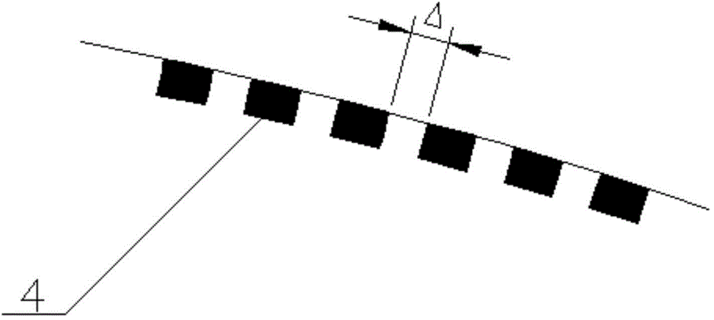
[0077] The circular code ring 17 is provided with a plurality of relative code tracks 7 on the inner surface 3 of the ring parallel to its axis, and a plurality of relative code tracks 7 include multiple groups of photoelectric sensors 4 evenly distributed around the circumference, and each group is distri...

Embodiment 2

[0090] This embodiment is basically similar to Embodiment 1, the difference is that "the DSP data processing unit 16 counts after receiving the time series pulse signal and the zero-crossing signal, and then calculates and obtains the rotation angle of the servo motor" as follows:

[0091] The DSP data processing unit 16 receives multiple groups of time sequence pulse signals and shapes them to obtain corresponding multiple groups of square wave signals. At the same time, after receiving the zero-crossing signal, it starts counting from zero. If more than two groups of square wave signals are detected at the same time The rising edge of the counting value is increased by 1, and finally the total counting value K is obtained, and the rotation angle of the servo motor is calculated according to the following formula:

[0092]

[0093] Wherein, θ represents the rotation angle of the servo motor, and N represents the total number of photoelectric sensors 4 of each relative code ...

Embodiment 3

[0097] A method for measuring a high-precision rotary encoder in Embodiment 1, comprising:

[0098] S1. Install a rotary encoder on the servo motor to be tested;

[0099] S2. The rotating shaft 14 of the rotary encoder rotates under the drive of the servo motor, so that the light emitted by the light source module 1 scans and irradiates a plurality of relative code tracks on the circular encoding ring 17 and the fixed zero code track 8;

[0100] S3. The photoelectric sensor on each relative code track successively senses light under the irradiation of light and generates a set of time sequence pulse signals, and the fixed zero code track 8 generates a zero-crossing signal under the irradiation of light;

[0101] S4, data acquisition module 15 is sent to DSP data processing unit 16 after collecting timing pulse signal and zero-crossing signal;

[0102] S5. The DSP data processing unit 16 counts after receiving the timing pulse signal and the zero-crossing signal, and then calc...


PUM


Abstract

The invention discloses a high-precision rotating encoder and a measuring method of the high-precision rotating encoder. The rotating encoder comprises an optical system, a round coding ring, a rotating shaft, a data collecting module and a DSP (digital signal processing) data processing unit, wherein the optical system comprises a plurality of light source modules uniformly distributed on the surface of the rotating shaft, the round coding ring and the rotating shaft are in coaxial arrangement, the round coding ring is provided with a plurality of opposite code ways on the inner side surface of the circular ring parallel to the axial line of the round coding ring, the gaps of photoelectric sensors of the opposite code ways are respectively identical, the round coding ring is also provided with a fixed zero position code way beside the opposite code ways, the fixed zero position code way consists of a photoelectric sensor, the fixed zero position code way and each opposite code way are respectively and independently connected with a data collecting module, and the data collecting module is connected with the DSP data processing unit. The high-precision rotating encoder and the measuring method of the high-precision rotating encoder have the advantages that measuring errors due to radial jumping can be avoided, the measuring precision is high, in addition, the anti-jamming and pollution-resistant capability is high, and higher reliability is realized. The high-precision rotating encoder and the measuring method can be widely applied to the field of rotating angle measurement.

Description

technical field [0001] The invention relates to the field of rotary encoders, in particular to a high-precision rotary encoder and a measuring method thereof. Background technique [0002] The motor of an AC servo motor is usually equipped with a photoelectric rotary encoder to measure the rotation angle of the motor. The photoelectric rotary encoder can obtain the rotation angle of the rotor to obtain the motor speed information, and the speed information can be fed back to the relevant speed control unit to accurately control the motor. At the same time, the movement displacement, speed, acceleration and other information of the actuator can be calculated indirectly. The positioning accuracy of the servo motor depends on the resolution of the encoder. Photoelectric rotary encoder is a sensor that converts the mechanical geometric displacement on the output shaft into pulse or digital quantity through photoelectric conversion. It is currently the most widely used sensor in...

Claims


Application Information

Patent Timeline
Patent Type & Authority Applications(China)
IPC IPC(8): G01D5/347
Inventor 王新力
Owner 海宁经开产业园区开发建设有限公司
Why Eureka
Try Eureka