Composite contactor

A composite contact and contactor technology, applied in the field of electrical switches, can solve the problems of limited inrush current suppression, long working time, large eddy current loss, etc., and achieves small contact bounce time, short conduction time, no Effect of Eddy Current Loss

Inactive Publication Date: 2011-01-19
GUANGZHOU JINSHI ELECTRONICS
View PDF0 Cites 21 Cited by
  • Summary
  • Abstract
  • Description
  • Claims
  • Application Information

AI Technical Summary

Problems solved by technology

[0002] At present, most of the loads in the power system are inductive loads, such as motors and various lamps with inductive ballasts. In order to save energy, reduce reactive power loss of the line, and improve the power utilization of power transformers, power capacitors are generally used in parallel in the line. As a power factor compensation, but due to the large impact current of the capacitor at the moment of connection, the contacts of the contactor are easy to burn and stick.
At present, there are special capacitor switching switches for capacitor switching in the market. One is an ordinary capacitor contactor (such as CJ19 series capacitor contactor). Auxiliary contacts, but they have limited ability to suppress the inrush current. When the load is put into the second time, the capacitor is required to be fully discharged. It cannot be broken when the current crosses zero. The arc is large when the capacitor is broken, and the operating life is not long. The contactor control coil For AC power supply, there are disadvantages of large eddy current loss, temperature rise, easy coil burning, and high energy consumption; another type of capacitor switching switch called a composite switch works by using a thyristor and a magnetic latching relay in parallel. , before the mechanical contact of the switch is turned on, the control circuit provides a trigger signal to the thyristor connected in parallel when the voltage at both ends of the mechanical contact crosses zero. The control circuit controls the mechanical contact of the magnetic latching relay to close; when the switch is broken, the control circuit triggers the SCR again, and then the control circuit controls the mechanical contact of the magnetic latching relay to break. After the mechanical contact is separated, the control circuit delays for a period of time. Turn off the thyristor trigger signal to complete the arc-free breaking process. Since there is a certain and uncertain value of breaking time in the mechanical contactor breaking, in order to ensure the reliable breaking of the arc-free purpose, it is necessary to separate the mechanical contacts. The thyristor needs to maintain a long conduction time, which has the disadvantages of long working time for the thyristor to be turned on when breaking, low power utilization rate of the thyristor, high heat generation, and reduced reliability. The power circuit or an additional auxiliary power supply is continuously supplied to the control circuit to ensure sufficient trigger energy to maintain the conduction of the trigger thyristor and the breaking of the mechanical contacts of the magnetic latching relay. , the problem of inconvenient use

Method used


Image

  • Composite contactor
  • Composite contactor
  • Composite contactor

Examples


Embodiment Construction

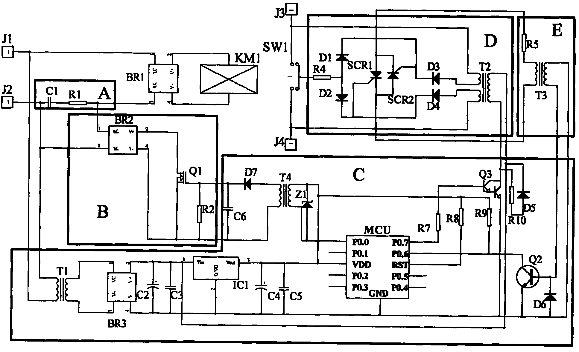
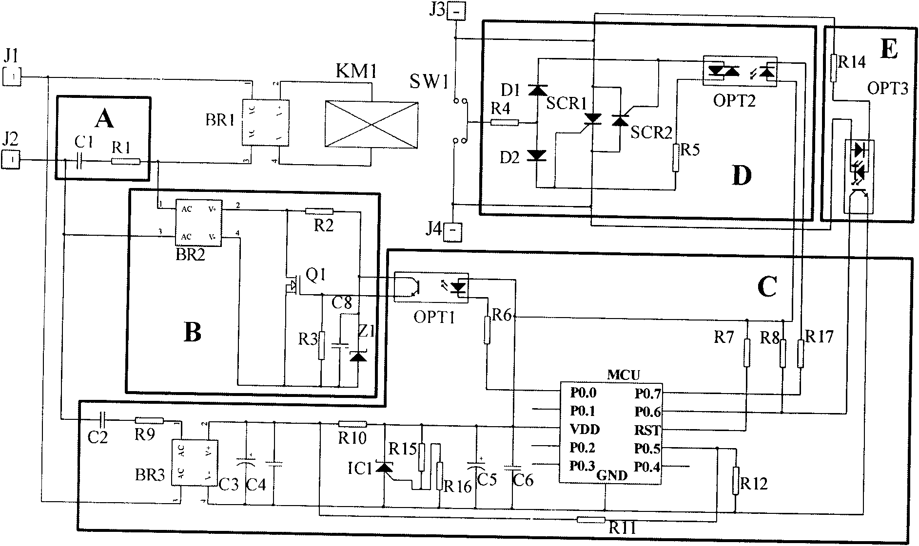
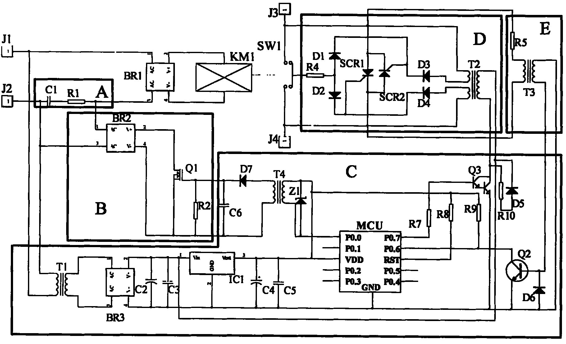
[0013] as attached figure 1 As shown, the AC power is input through the J1 and J2 ports, and then the current is limited by the capacitor voltage drop circuit (A), rectified by the rectifier circuit BR1 to supply power to the contactor control coil KM1, and the capacitor voltage drop circuit (A) is connected in parallel with the starting electronic switch (B ), start the electronic switch (B) and connect the control end to the control circuit (C), connect the working power end of the control circuit (C) to the power input ports J1 and J2, and the voltage zero-crossing detection circuit (E) and the thyristor circuit ( D) Connected in parallel at both ends of the input and output terminals J3 and J4 of the mechanical contacts of the contactor, the output terminal of the voltage zero-crossing detection circuit (E) and the conduction control terminal of the thyristor circuit (D) are connected to the control circuit (C), which can be controlled The other conduction control end of t...


PUM


Abstract

The invention relates to a composite contactor which belongs to the field of electric switches, in particular to a contactor suitable for powering on and off a power capacitor. In the invention, an input power supply is subjected to current limit by a capacitor voltage drop circuit and rectification by a rectifying circuit and used for supplying power to a control coil of the contactor; the capacitor voltage drop circuit is connected with a starting electronic switch in parallel, the control end of the starting electronic switch is connected to a control circuit, and the control circuit is connected with a working power supply; a voltage zero passage detection circuit and a controllable silicon circuit are connected to two ends of a mechanical contact of the contactor in parallel; and the output end of the voltage zero passage detection circuit and one on control end of the controllable silicon circuit are connected to the control circuit, while the other on control end of the controllable silicon circuit is connected to a contact bridge of the contactor. The control coil of the composite contactor adopts a capacitor voltage drop direct current working manner, and the controllable silicon circuit adopts a design with multiple control ends, so that the composite contactor has the advantages of environmental protection, energy saving, strong anti-jamming, power on work, power on with voltage zero passage, power off with current zero passage, short controllable silicon on time, high reliability and long operation service life.

Description

technical field [0001] The composite contactor of the invention belongs to the field of electric switches, in particular a contactor suitable for connecting and disconnecting power capacitors. Background technique [0002] At present, most of the loads in the power system are inductive loads, such as motors and various lamps with inductive ballasts. In order to save energy, reduce reactive power loss of the line, and improve the power utilization of power transformers, power capacitors are generally used in parallel in the line. As a power factor compensation, but due to the large impact current of the capacitor at the moment of connection, the contacts of the contactor are easy to burn and stick. . At present, there are special capacitor switching switches for capacitor switching in the market. One is an ordinary capacitor contactor (such as CJ19 series capacitor contactor). Auxiliary contacts, but they have limited ability to suppress the inrush current. When the load is...

Claims


Application Information

Patent Timeline
Patent Type & Authority Applications(China)
IPC IPC(8): H03K17/72H03K17/78H01H47/00
Inventor 郭桥石
Owner GUANGZHOU JINSHI ELECTRONICS
Why Eureka
Try Eureka