
Cylinder type deep well rescue device

A deep well and barrel-type technology is applied in the field of barrel-type deep well rescue devices, which can solve the problem that the rescue device cannot be rescued in a timely and effective manner, and achieve the effects of simple structure, strong applicability and high degree of automation.

Active Publication Date: 2018-07-31
SOUTHWEST JIAOTONG UNIV
View PDF5 Cites 7 Cited by
  • Summary
  • Abstract
  • Description
  • Claims
  • Application Information

AI Technical Summary

Problems solved by technology

[0003] The main purpose of the present invention is to provide a cylindrical deep well rescue device to solve the problem that rescue devices in the prior art cannot be rescued in a timely and effective manner

Method used


Image

  • Cylinder type deep well rescue device
  • Cylinder type deep well rescue device
  • Cylinder type deep well rescue device

Examples


Embodiment 1

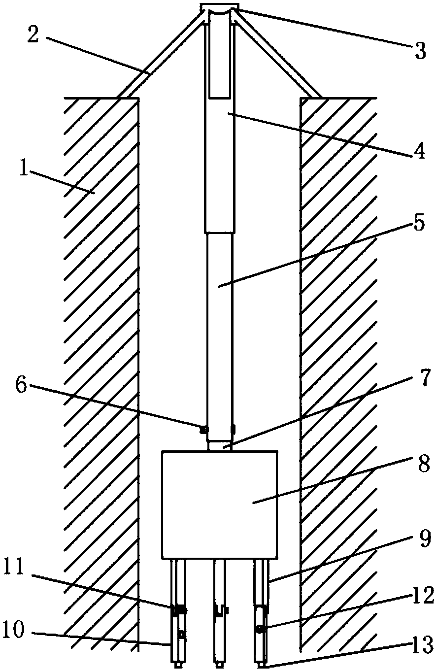
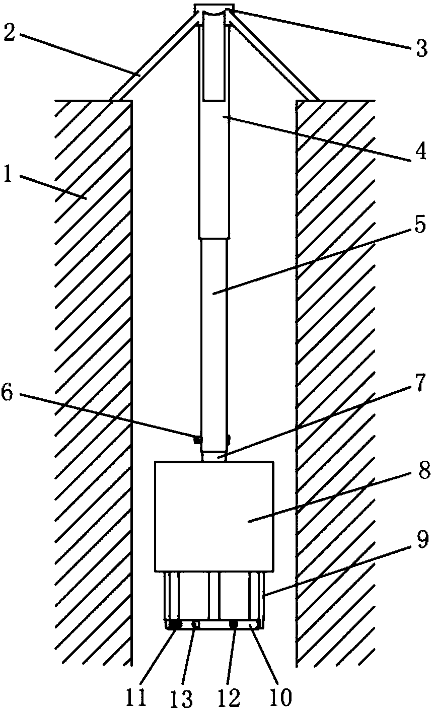
[0048] Such as Figure 1-3 The shown cylindrical deep well rescue device includes a main support structure 2 connected to the entrance and exit of the deep well 1, a safety sleeve 8, and a device that is located between the main support structure 2 and the safety sleeve 8 and controls the lifting of the safety sleeve 8. A control mechanism and a self-locking support mechanism located below the safety sleeve 8;

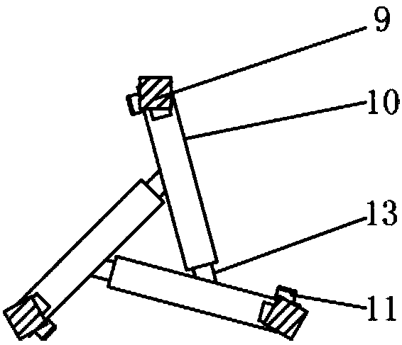
[0049] The self-locking support mechanism includes three self-locking units; the self-locking unit includes a first folding rod 9, a second folding rod 10 hinged to the first folding rod 9, and drives the second folding rod 10 along the a drive 11 to rotate at its junction with the first folding lever 9;

[0050] The bottom of the second folding rod 10 is provided with a first latch 13, and the middle part is provided with a socket 12 matching the first latch 13, and the second folding rods 10 of the adjacent self-locking units pass through the mutual The matched fir...

Embodiment 2

[0056] Compared with Embodiment 1, the difference that the cylindrical deep well rescue device of this embodiment has is: as Figure 4-5 As shown, there are four self-locking units, and the included angle between the socket 12 and the axial direction of the second folding rod 10 is 90°; it also includes a connection structure connecting the self-locking support mechanism and the safety sleeve 8 , the connecting structure is a protruding strip 81 provided on the inner wall of the safety sleeve 8 , and the first folding rod 9 is provided with a slide groove 91 matching the protruding strip 81 . When the safety sleeve 8 falls to cover the well faller, the first folding rod 9 will move down along the chute 91 .

Embodiment 3

[0058] Compared with Embodiment 1, the difference that the cylindrical deep well rescue device of this embodiment has is: as Figure 6 As shown, the protective structure is also included.

[0059] The inner side of the first folding rod 9 is provided with an installation groove 92 , and the protection structure is an airbag arranged in the installation groove 92 .


PUM


Abstract

The invention discloses a cylinder type deep well rescue device which comprises a main support structure connected with a deep well access, a safety sleeve, a control mechanism located between the main support structure and the safety sleeve and used for controlling the safety sleeve to lift up and down, a self-locking support mechanism located under the safety sleeve, and a connecting structure connected with the self-locking support mechanism and the safety sleeve. The self-locking support mechanism comprises at least two self-locking units; each self-locking unit comprises a first folding rod, a second folding rod hinged with the first folding rod, and a driver for driving the second folding rod to rotate along a connecting part between the second folding rod and the first folding rod;a first bolt is arranged on the bottom part of each second folding rod; an inserting port matched with each first bolt is formed in the middle of each second folding rod; and the second folding rods of the adjacent self-locking units realize self-locking connection through the first bolts and the inserting ports matched mutually. The whole device is simple in structure, convenient to install and high in applicability, and can buy precious rescue time for people falling into the well.

Description

technical field [0001] The invention relates to the technical field of deep well rescue, in particular to a cylindrical deep well rescue device. Background technique [0002] Due to the limitations of the size of the rescuers, the diameter of the deep well, and the geology, the rescue process consumes a lot of manpower, material and financial resources. Simultaneously, the time required for the installation of the existing rescue device is longer, which delays the golden time of rescue, the survival rate of the rescued is low, and it is easy to cause secondary injury to the person who fell into the well during the rescue process. At this stage, no good solution has been found for small-caliber deep well rescue, so timely and effective rescue cannot be carried out. Contents of the invention [0003] The main purpose of the present invention is to provide a cylindrical deep well rescue device to solve the problem that rescue devices in the prior art cannot perform timely an...

Claims


Application Information

Patent Timeline
Patent Type & Authority Applications(China)
IPC IPC(8): A62B99/00
CPCA62B99/00
Inventor 张则强龚举华贾林李云鹏曾艳清程文明
Owner SOUTHWEST JIAOTONG UNIV
Learn More